Loading...
Loading...
Loading...
Loading...
Loading...
Loading...
Loading...
Loading...
Loading...
Loading...
Loading...
Loading...
Loading...
Loading...
Loading...
Loading...
Loading...
Loading...
Loading...
Loading...
Loading...
Loading...
Loading...
Loading...
Loading...
Loading...
Loading...
Loading...
Loading...
Loading...
Loading...
Loading...
Loading...
Loading...
Loading...
Loading...
Loading...
Loading...
Loading...
Loading...
Loading...
Loading...
Loading...
Loading...
Loading...
Loading...
Loading...
Loading...
Loading...
Loading...
Loading...
Loading...
Loading...
Loading...
Loading...
Loading...
Loading...
Loading...
Loading...
Loading...
Loading...
Loading...
Loading...
Loading...
Loading...
Loading...
Loading...
Loading...
Loading...
Loading...
Loading...
Loading...
Loading...
Loading...
Loading...
Loading...
Loading...
Loading...
Loading...
Loading...
Loading...
Loading...
Loading...
Loading...
Loading...
Loading...
Loading...
Loading...
Loading...
Loading...
Loading...
Loading...
Loading...
Loading...
Loading...
Loading...
Loading...
Loading...
Loading...
Loading...
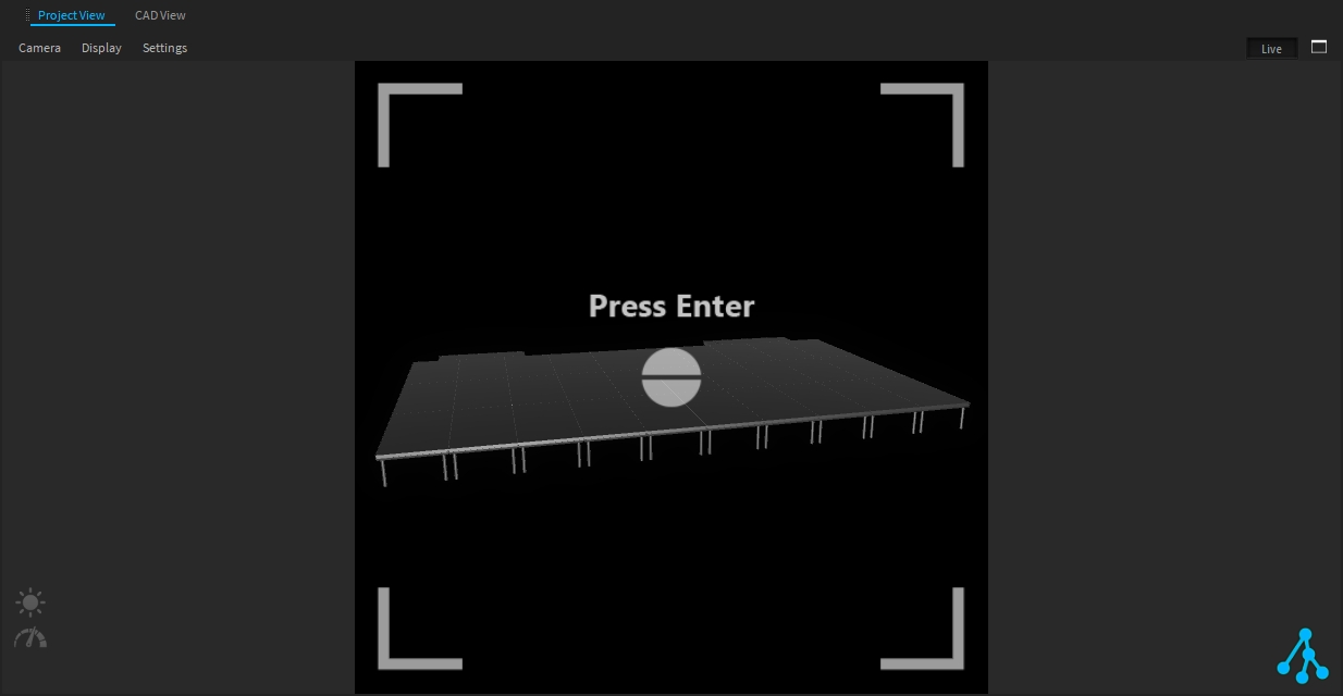
Depence comes with two render modes, "Photo Realistic" and "CAD View". Within the Render Window Menu, you can change the current mode by using the "Display" menu item. Please note that only one "Photo Realistic" view can be activated at a time.
Each Render View has a Live-Mode button, which enables a non-editable mode in the currently active editor. This is perfect for show programming. If the live-mode is active, only fixtures can be selected.
Depence can also be started with command-line arguments. Using these commands, you can enable or disable different options.
Depence.exe -No3D
Prevents Depence from starting with the 3D engine. This might be necessary if Depence is used only as a control on a non-graphics-capable laptop.
Depence.exe "C:\DepenceProjects\MyProject\MyProject.depence"
Starts Depence and automatically loads the project file specified in quotes.
Depence.exe -FullScreen 0
(Only in combination with loading a project directly) Opens the fullscreen view on the specified monitor (0, 1, 2, n), with 0 being the main monitor where Depence starts.
Depence.exe "C:\DepenceProjects\MyProject\MyProject.depence" -FullScreen 0
Opens the project and displays it in fullscreen on the main monitor.Depence is an unique software application, which combines the design and visualization process with tools to control the real show. The rendering engine of Depence uses latest technologies to simulate multimedia installations with realistic results. With show design becoming more and more complex, utilizing more and more varieties of different elements and media, Depence is the ideal system to control and pre-viz your entire show. All physical and controlling characteristics of the equipment are simulated with real-time accuracy. Depence eliminates the guess work out of visualizing your designs.
With a clear focus on creating perfectly synchronized multimedia shows, Depence features a user-friendly workflow to program complex shows in a visual timeline environment, combined with a real-time 3D viewer. Powerful automation and logic features in combination with our stand-alone hardware playback servers provide all you need to bring your show to life.
For more info about the product visit www.syncronorm.com
The Depence installer will automatically create a "Depence_Data" folder in your Windows Documents folder.
This folder is intended to store all your Depence Projects. This folder location can be changed from Application Settings > Globals > User Work Path.
Depence will create a new sub-folder for each project including all used resources. The Software will not link to files on your disk.
This makes it easy to share projects with other computers.
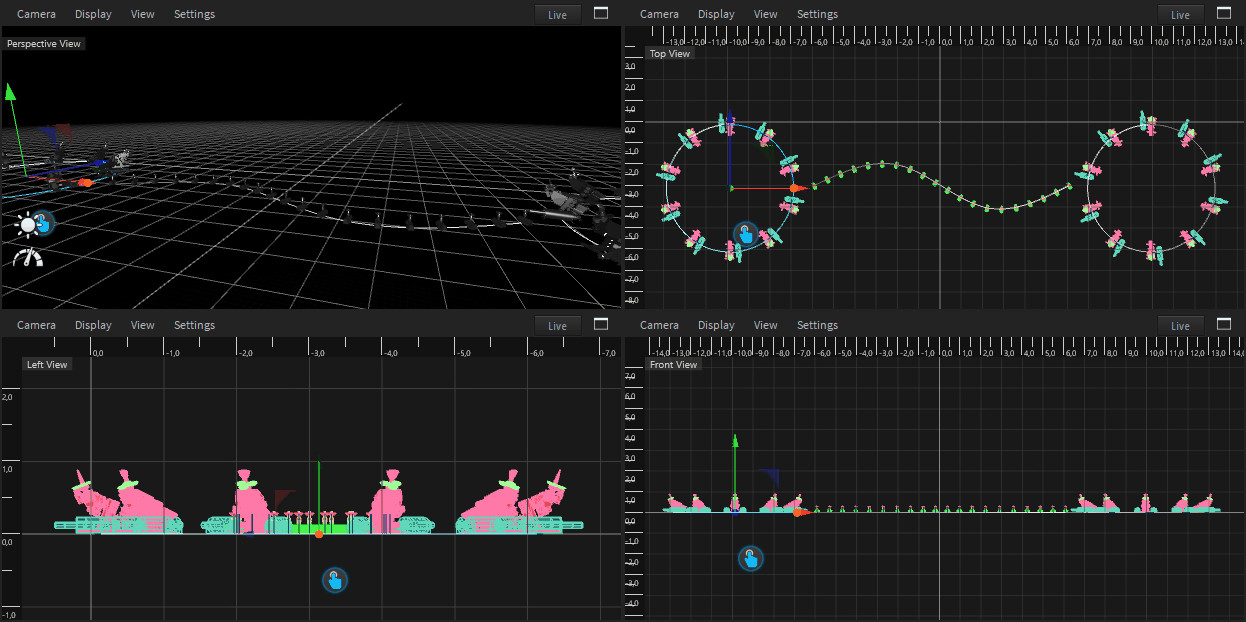
To open the Quad View click the Quad View button on the top right corner of your Render View.
The Quad View will split the view into four views, which can be configured independently.
Within the camera menu, you can change the current perspective as well as the projection mode. To switch your view to full screen click on the Quad View icon.
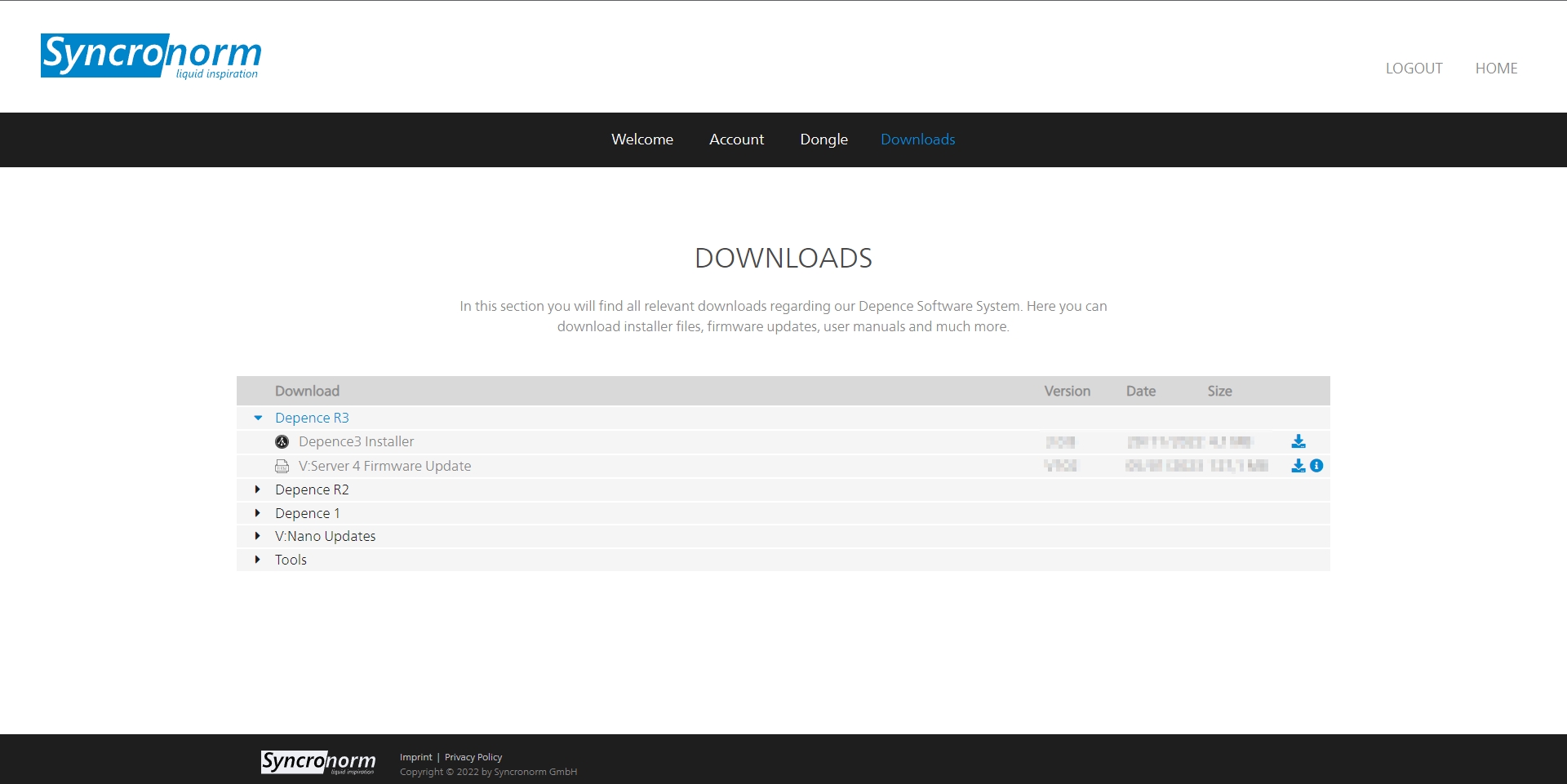
Connect to your Syncronorm account to access the download page of Depence and obtain the latest Software installer:
The Installer will automatically collect the latest available software version and install it on your system.
Important: An Internet connection is required during the entire installation process!
Since Depence is a graphically intense software, it requires a powerful graphic card. In case your computer has more than one graphic adapter installed (which is often the case on laptops), you need to make sure that Depence will run on the most powerful card installed.
On NVIDIA-based systems, you can select the "default" graphics hardware within the NVIDIA system configuration.
Please keep your graphic card drivers always up-to-date.
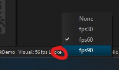
The Depence render window always tries to render at the same framerate (fps) as your monitor refresh rate. This synchronization is called V-Sync. Usual monitors are working with a 60Hz refresh rate but modern gaming monitors and even gaming laptop screens are more and more shipped with high-frequency monitors with 120, 140, or even 200 Hz.
That means on a 140Hz Screen, the V-Sync tries to match Depence's frame rate to 140fps.
While this improves the subjective smoothness of animations, it drastically stresses your hardware. This results in GPU overheating/throttling and low battery life on laptops.
Therefore Depence has a feature called Frame-Limiter, which can limit the fps to a specific value. You can apply a frame limiter in the Application Settings or by a click on the framerate in the window's status bar:
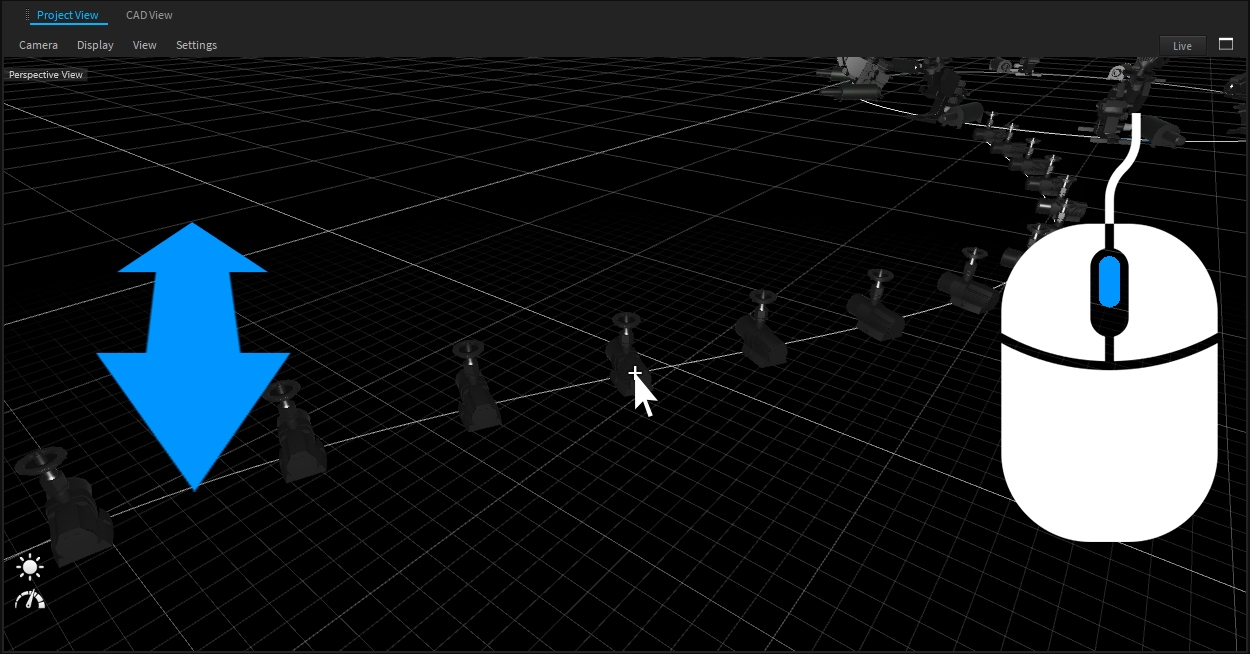
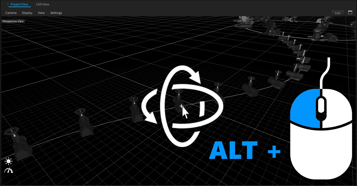
The Camera in Depence is optimized to be easily navigated through bigger scenes or even rotate around a specific object.
Focus your camera at the point of interest and use your Scroll-Wheel on your mouse to zoom in or out.
To rotate your camera around your focused point hold ALT and your left mouse button or the middle mouse button/scroll wheel. The Camera will try to rotate around the intersection point of your scene. If no intersection is found (e.g. when clicking on the sky) the camera will rotate around itself.
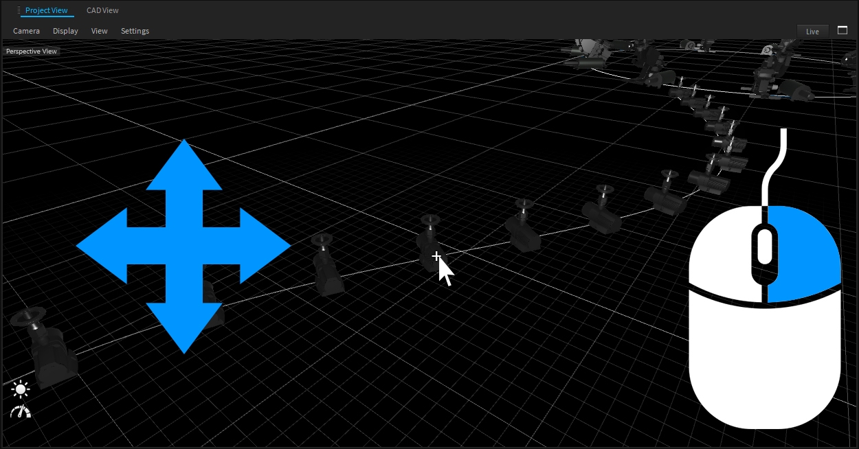
To move your camera in view-space hold your right mouse button while moving the mouse.
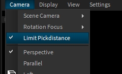
The editor limits the distance to an intersection point, which is too far away, to prevent accidental movements by default. However, in some cases, like in terrain sculpting or Fireworks, it might be required to disable this limit. Therefore go to the View-Menu and disable "Limit Pick Distance" in the camera menu.
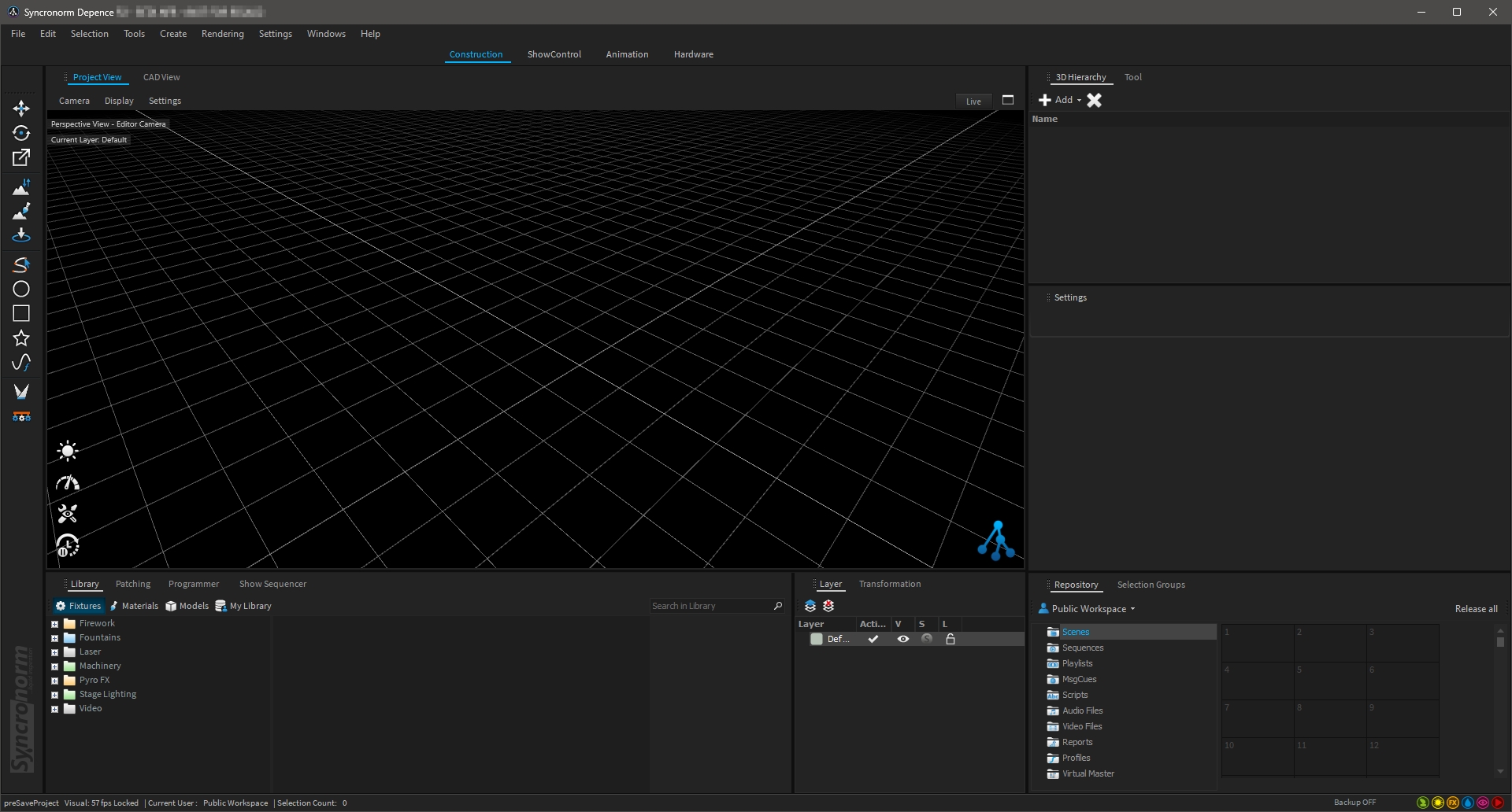
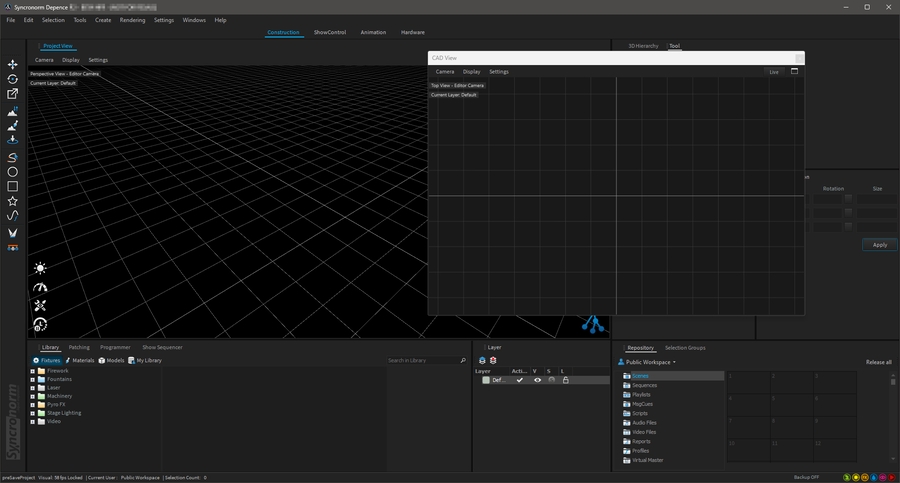
All Depence windows are placed in flexible and customizable workspaces.
Default workspaces are Construction, Show Control, Animation and Hardware. Each workspace will show up and align in the required windows in the most effective way.
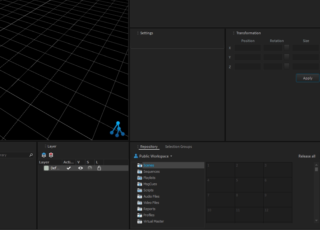
Each window can be dragged into other windows or be extracted as a floating window, to be used on multi-screen monitor setups:
A floating window remembers its position. Double-click on the window title to toggle the floating mode!
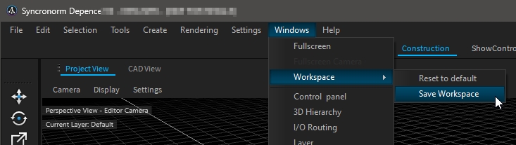
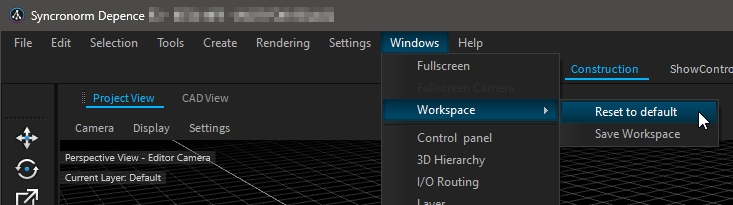
To store your changes on the current workspace go to: Windows > Workspace > Save Workspace.
Reset to default To reset a workspace to the default setup, go to Windows > Workspace > Reset to default.
Intention and functionality of the most important windows:
Project View This window contains the rendering views as well as all 3D editor functionality.
CAD View The CAD View window is a second render-view in form of a wireframe view of your current scene.
Library The Library window provides access to the installed asset library. Here you can find all fixtures, materials, and models.
Settings The Settings window is one of the most important windows in Depence. It shows the settings of the currently selected object. This can be a fixture or a scene within the timeline.
3D-Hierarchy This window displays the 3D Scene-graph organization of your project. More information in .
Tool Once a tool is selected, most have specific settings, which can be adjusted here.
Repository The Repository window contains all show-programming related objects like Shows, Scenes, and more.
Programmer By using the programmer you can change the values of currently selected fixtures and finally create scenes for the repository or a timeline show.
Selection Groups This window will show up all fixture selections.
Patching The Patching window shows all patched fixtures on all universes.
Fixture Manager
The window allows managing, viewing, and exporting information about the project's fixtures.
DMX-View The DMX-View shows real-time information about the current DMX-buffer
Layer The Layer window provides access to all 3D layers. More information in .
Show Sequencer This tool contains the show timeline to create and edit your shows.
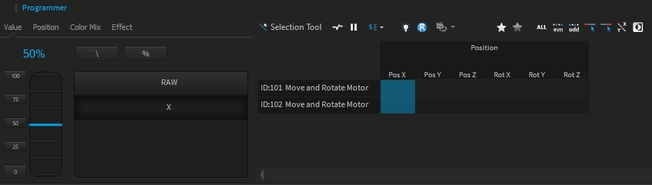
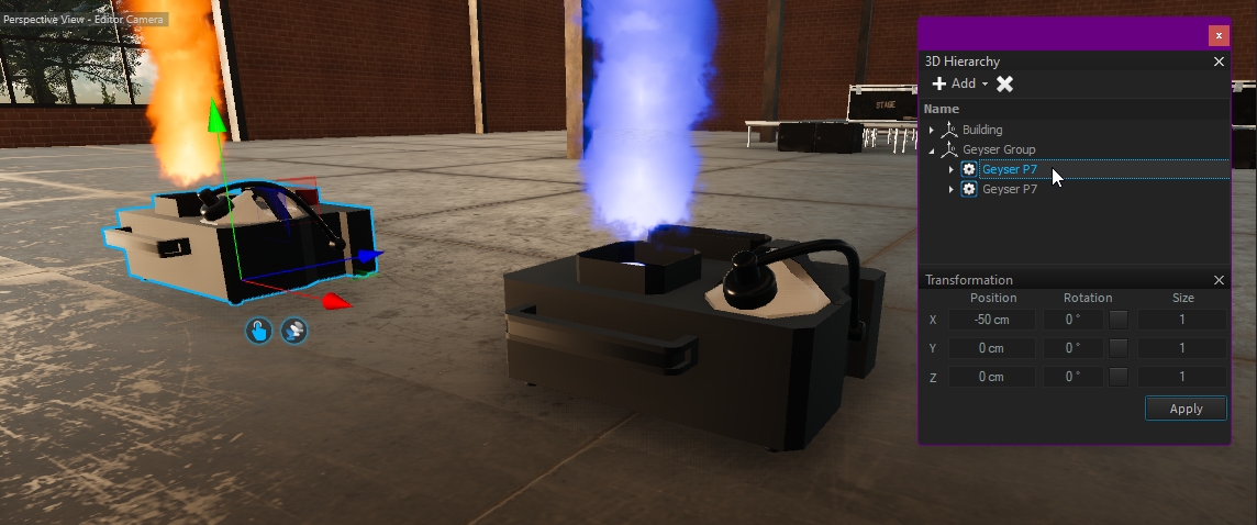
Transformation
This Transformation window shows the current selection transformation. More information in .
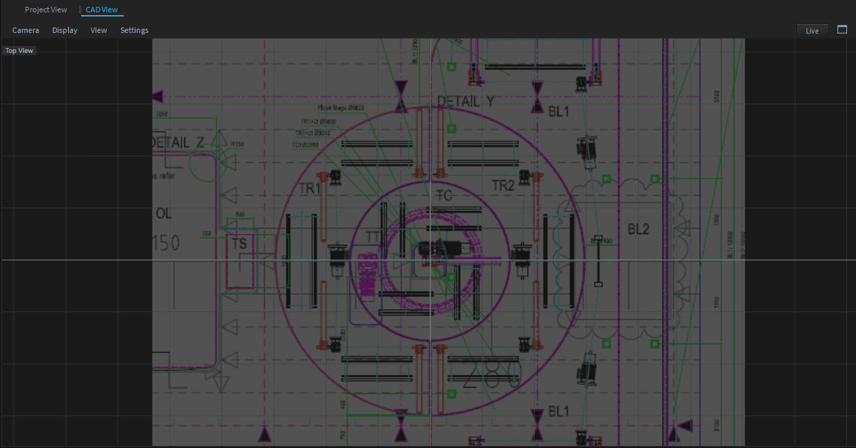
The CAD-View offers the possibility to add a background image in the correct scaling, which can help while working on a specific plan. To add a background image, follow these steps:
Click on the Settings menu item in the CAD-View Window.
Within the Settings Window you can see the Settings of this CAD-View.
Load your image via the Background Image property.
To scale your image to the right size, you can easily pick a distance and center on the image and it will stretch the background image accordingly.
Within the CAD-View Menu > Display > Fit Background Image.
Pick a known distance for your image (this might be any scaling info).
Now enter the correct distance.
Pick the center.
The necessary system performance depends on the size of the project you are working on. While Depence is a graphically intense software, the graphics hardware is of course one of the most important components. Depence also takes advantage of multi-core CPUs.
Microsoft® Windows® 10/11 64-Bit
CPU's with high single thread performance
16 GB RAM
Dedicated gaming graphic card with min 6GB VRAM
One free USB port for USB-License Dongle
Microsoft® Windows® 11 64-Bit
Intel i9-13900K or AMD Ryzen 9 7950X
64 GB RAM
NVIDIA RTX4080, RTX4090 or latest
One free USB port for USB-License Dongle
Fast SSD Drive
Since Depence R4 and Windows 11 version 24H2, it is possible to install and run Depence on a machine with an ARM CPU. This also includes Apple computers with Apple Silicon using Parallels Desktop with latest Windows 11 ARM.
This is currently in an experimental state! Crashes or poor performance may occur!
Image Format
File extension
Recommended
Notes
JPEG-Image
*.jpg
✔
Bitmap 8-bit
*.bmp
✔
PNG
*.png
✔
DDS
*.dds
✔
Targa
*.tga
✔
OpenEXR
*.exr
✔
HDR Image format
HDR Image
*.hdr
✔
HDR Image format
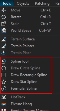
The Editor consists of multiple tools to manipulate objects. You can select the tool from the left Toolbar visible in the Construction Workspace or in the Main menu under "Tools". The ESC-Key on your keyboard will always exit the current tool and activate the Move-Tool as a default tool.
Depence offers several manual and procedural spline objects, which can be used to fast arrange objects in any shape.
A Camera Video Source renders the scene from the perspective of a current camera, which is selected by a defined camera selector. This allows for real camera movements to be displayed on video screens.
Proceed as follows:
Create one or multiple Camera Objects and place them into your scene
Create a Camera-Selector Object (Create > Scene > Camera Selector)
Go to Settings > Video Sources...
Click on the "Add" Button and choose "Camera Video Source"
Once selected, pick the Camera-Selector object from the drop down
check Active
Now you can use this Video-Source on any Texture or Projector.
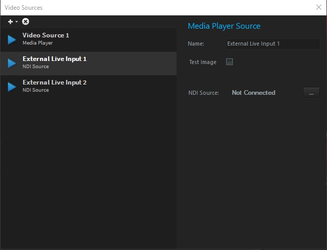
Depence offers several ways to display Video Content within your 3D environment. A Video Source defines the source of a Video Signal, which can be further assigned to Video Projector fixtures or Materials (f.e. to map on displays and screens).
To open the Video Source list go to the Main menu > Settings > "Video-Sources..".
Depence offers two different Video Source types, the Media-Player Source or NDI Video Source.
The NDI Video Source provides live video streaming via Ethernet, using the NewTeks NDI Streaming Protocol. Several other products in media technology also support NDI, e.g. Resolume, VLC Player, and many more. Using the free available NDI Tools, it is also possible to easily grab any screen on a computer in your local network, to use as a live video source.
Here you can find out more:
3D-Format
File extension
Recommended
Known Limitations
Collada
*.dae
✔
3D Studio Max 3DS
*.3ds
Texture file names are limited to 8 characters
No normals are stored
Sketchup 2019
*.skp
✔
Wavefront Object
*.obj
✔
Autocad DXF
*.dxf
Only 2D
Under development
LightWave Model
*.lwo, *.lws
DirectX 3D mesh
*.x
Stereolithography
*.stl
AC3D
*.ac
3D Studio Max ASE
*.ase
Autodesk FBX
*.fbx
✔
To disconnect all connectors on fixtures, select the fixtures right-click > Disconnect.
Firework effects in Depence are following the same concept as other devices as they are fixtures. This makes it possible to fire individual effects directly via DMX trigger.
If you directly drag a firework effect into the world it will create a fixture and patch a single DMX channel. You can fire the effect once or multiple times by triggering the DMX value (>128).
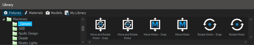
To make the creation of firework effects easier, Depence comes with so-called "Generic" objects, which automatically create and set up the necessary particle emitters behind, based on simple and known properties.
These Generic Objects represent basic firework bombs that are scaling in size defined by the caliber.
Usually, all permutations of these Generic Effects are already existing in the factory library, but you can easily use this object to let Depence create some basic particle emitters and settings for you as a good starting point.
To break down a Generic object into the final objects, do a right-click in the 3D-Hierarchy and choose "Breakdown".
Custom firework effects can be built using the Depence asset builder, which gets installed alongside with Depence.
Go to New > New Firework Effect...
A fixture and DMX-Ignition object along with the default DMX mode has been created automatically.
Save your fixture into your MyLibrary folder: Documents\Depence\MyLibrary\Firework\
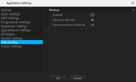
Depence has a feature to frequently save your project as a backup automatically.
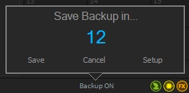
For this purpose, you will find the information "Backup Off" or "Backup On" in the lower status bar. You can click on this label to change the status from Backup Off to Backup On.
When a backup is executed, another subfolder "Backup" is automatically created in the project folder and the current project status is saved there.
You can set the options for the interval and the lead time at which a backup is to be created in the Application Settings.
Before the system creates a backup, a countdown dialogue appears in which you can cancel the process with "Cancel" or carry out the backup process again with "Save". You can change the settings with "Setup".
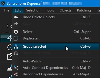
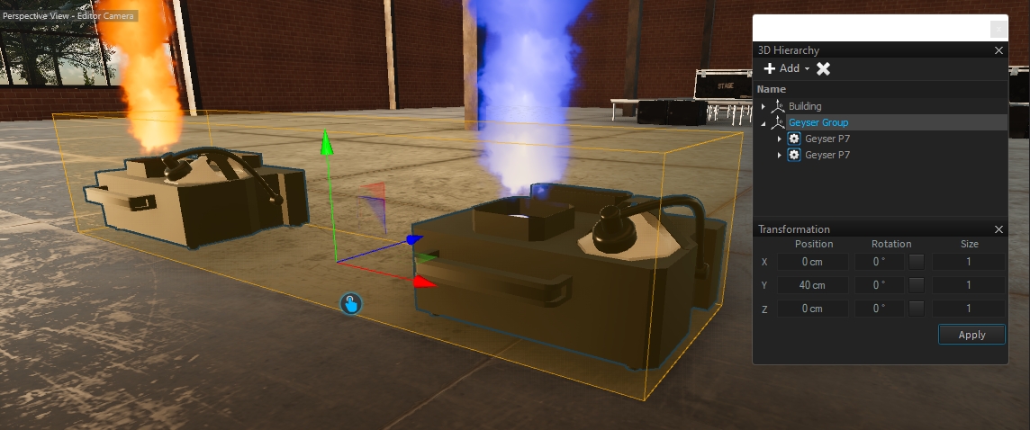
When grouping objects, child objects will be assigned to all objects of a single group-object. This will help to organize your scene. Once you have selected more than one object, you can use CTRL+G, right-click > Group Objects, or from the Edit menu:
Once objects are grouped, their child objects can't be selected as usual with a single click. Therefore the editor can "jump" into each level of grouping to still be able to change children of groups. A simple double-click on a grouped object will open the group and disable all other items outside the group.
The orange highlighted editor will indicate that you are within a group. Use the ESC Key on your keyboard to leave the group.
The CAD Editor Snapping feature, introduced from Depence R4, enables effortless and precise object alignment and snapping:
This tool is exclusively available when using one of the predefined views:
Holding the SHIFT or ALT key while dragging an object offers additional control:
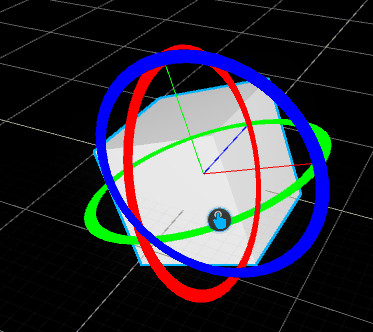
Shortcuts: CTRL+E or E
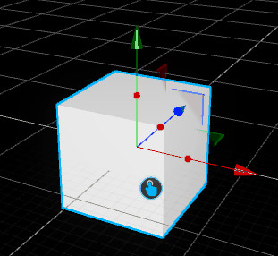
The Move Pivot tool translates/moves the positions of the objects. Furthermore, it can contain pick-points to change specific object properties depending on the object type.
To move an object on a specific axis, click on one of the arrows and move your mouse. Using the Plane movers you can move the object on two axes at the same time.
Holding the SHIFT key on your keyboard while moving, the object will snap in a 10cm grid.
While holding the CTRL key and moving the object, it will automatically create a copy of your selection.
This tool will draw a circle or ellipse spline. Select the Circle Spline tool on the left toolbar.
Click and hold your left mouse button for the first point.
Move your mouse to extend the circle.
Release the mouse button to create the spline.
Hold CTRL to keep the center on the first position you have clicked. Hold SHIFT to lock Radius X and Y to create a perfect circle.
Ellipse
Sets & locks Radius and RadiusY at the same value.
Min / Max Angle
Defines the start and end angle of the circle.
Point Count
Amount of interpolation points.
Radius
Horizontal Radius.
RadiusY
Vertical Radius.
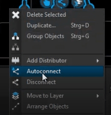
Once you need to connect multiple fixture pairs it can be time-consuming to do this manually one by one. You may use the auto connection function instead. It automatically searches for open connectors and tries to connect fixtures one by one. Please note that this feature cannot automatically connect a whole setup. It always requires the same amount of active and passive fixtures to work correctly.
To automatically connect your fixtures do as follows:
Select your Active and Passive Fixtures.
Right Click > Autoconnect.
The Selection Tool can also be used via left mouse button while the Move-Tool is active.
Each object can be selected with a single click, by using the left mouse button. By holding the left mouse button you can draw a selection rectangle to select all objects within that area. Hold CTRL or SHIFT key to add further selections.
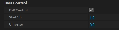
The diffuse color of the PBR Material can be directly controlled by values (RGB) from the internal DMX Buffer. This makes it possible to quickly realize LED surfaces/objects.
You can patch the DMX Matrix fixture with the RGB profile to control the color material emission.
Please note that the Universe value is zero-based.
This feature is deprecated and will be removed in a future version. Please use the DMX Matrix feature which has more possibilities.
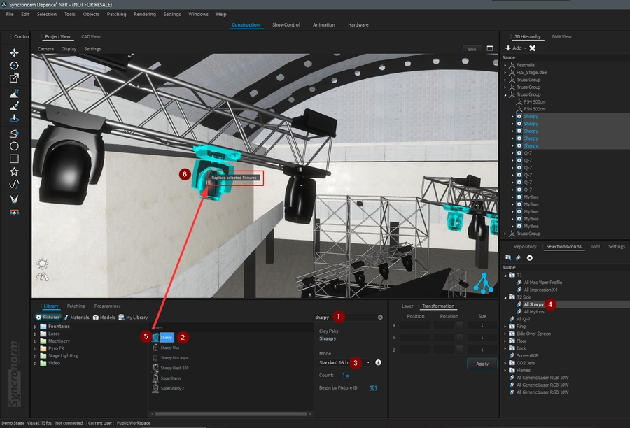
To replace a fixture:
Search the new fixture in the library.
Select the new fixture from the result list.
Set the DMX mode to be used.
Select the current fixture(s) to be replaced (from a group, 3D Hierarchy, or Project View).
Drag the new fixture on top of one of the currently selected fixtures.
Drop the new fixture when “Replace Selected Fixtures” appears.
If you are sure, you can validate the replace action:
Following your current patch and changes performed by the replacement action, Depence will indicate patch conflicts:
Patch on the next free addresses will patch your new fixture(s) on the next free addresses of your patch
Unpatch existing fixtures will unpatch existing fixture in conflict with your new fixture
Patch with overlapping addresses will patch at the current address with overlapping other fixtures (used to patch several fixtures at the same address)
It's done! Your new fixture(s) has now replaced the previous one.
First make sure you are using a Lasergraph DSP, which has the newest system software (min 2014) from Laseranimation Sollinger.
Start Depence and boot the DSP.
Start the LGRemote Software and connect to your DSP.
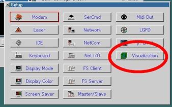
Type "setup" into the command line to show the setup window.
Click on "Visualization".
Select "Depence V3D" like software.
The checkbox below will activate the laser output.
You can set the Laser Source Output Index within the edit box to which the DSP will send data. This is comparable to the Realizzer Laser Source Number.
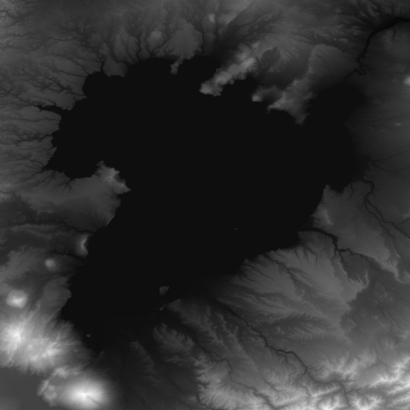
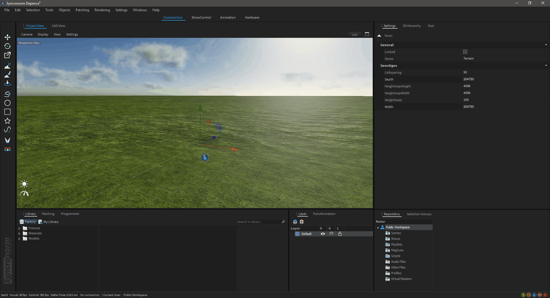
The Depence rendering engine offers real-time tessellated terrain sculpturing and atmosphere scattering to render realistic outdoor scenes. To create terrain and an atmosphere click on Main Menu > Objects > Create Environment.
This will automatically add a terrain and atmosphere object to your scene.
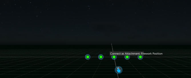
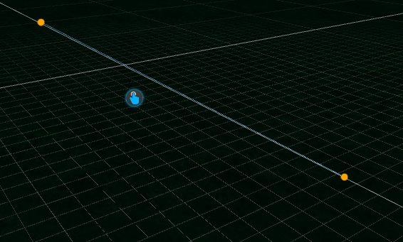
If you want to fire many shells along a line, you can create many firework-positions and arrange them on a line. However, this will create many timeline tracks and events, which also has a higher performance impact. In this case it is better to use a Spline instead of a single Firework-Position.
Create a simple Spline using the Spline tool.
Add a Firework-Position object next to the Spline.
In the 3D-Hierachy window drag the Spline into the Firework-Position.
Every stepper event, which is now applied to this position will be arranged along the spline.
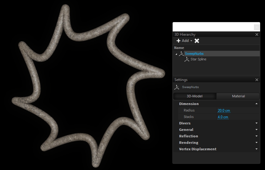
This tool will draw a Star spline. Select the Star Spline tool on the left toolbar.
Click and hold your left mouse button for the first point.
Move your mouse to extend the star.
Release the mouse button to create the spline.
Hold CTRL to keep the center on the first position you have clicked.
Inner Radius
Defines the inner radius of the Star.
Outer Radius
Defines the outer radius of the Star.
Points
Amount of edges.
Twist
Axially rotates the edges.
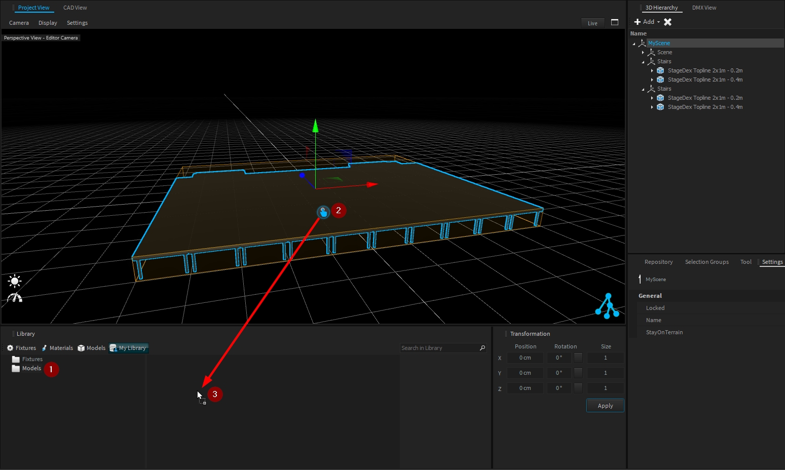
Depence offers several ways to place objects into your scene. The most common way is using Drag & Drop.
Once you have selected a fixture you can select the DMX mode and number of fixtures, then just pick the item and drag it into your 3D-World. If you have chosen an amount of more than 1 and drag over a spline object, the software will offer you to align the new objects on this spline after the drop.
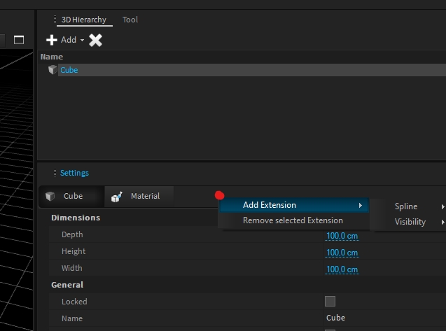
All objects, 3D-Models, Fixtures, Lights, etc... have several properties for their specific requirements. An Extension can add further functionality and settings to an object.
This also allows us to add more tools and features without touching and overloading existing objects.
To add an extension to any object, right-click on the tab bar within the Settings window and choose Add Extension.
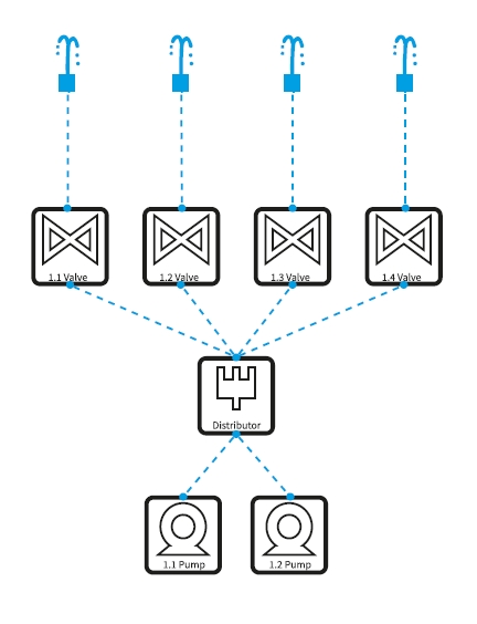
Dependencies are logically connected between fixtures. These can share information on water (pressure, flow rate, etc), lighting or power. Dependencies are elemental, especially for fountain devices.
A classic example: Nozzles connected to valves, which are further connected to a water distributor, which gets finally powered by one or more pumps.
In general, there are two types of fixtures:
Active Fixtures: All fixtures, which are delivering information and are usually DMX controlled like pumps or valves.
Passive Fixtures: All fixtures, which do only have dependency connectors waiting for an input signal. Like nozzles.
Passive fixtures, which are added to the scene, will always simulate input of 100% until they get connected to an active fixture. For example, a nozzle fixture will emit water even if it's not connected to a pump. This behavior makes the scene-building process easier.
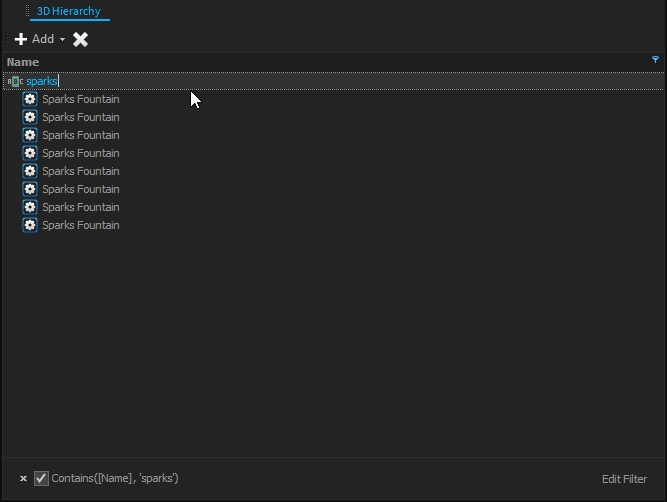
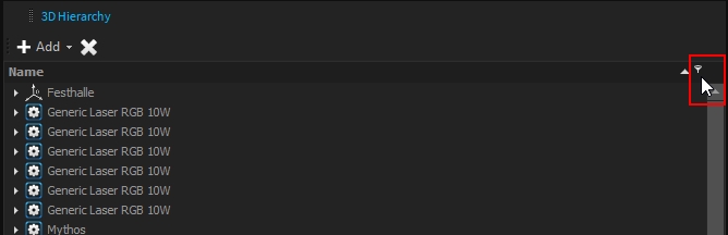
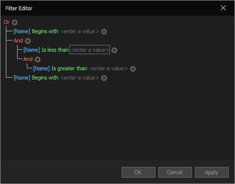
On a scene graph, it is important to be able to retrieve the object quickly and easily. For that purpose, filters are available in the 3D Hierarchy window:
Several filters are available, from the simplest to the more advanced ones.
The simplest one is directly accessible when hovering over the "Name" through the filter icon:
This filter already provides several basic filters type:
Right-clicking the "Name" label provides access to other filters of the 3D Hierarchy:
E.g. the "Auto Filter Row":
More advanced filters are available within the "Filter Editor", allowing you to create a block of a filter with advanced conditions:
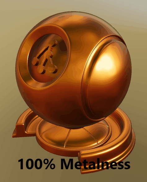
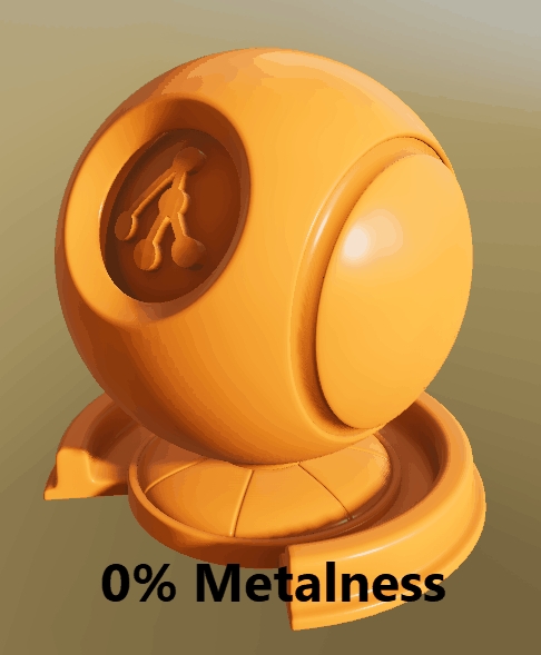
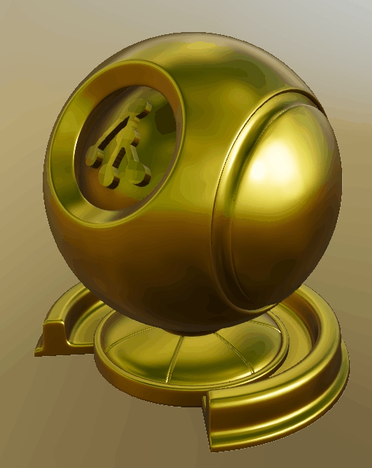
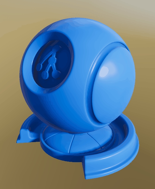
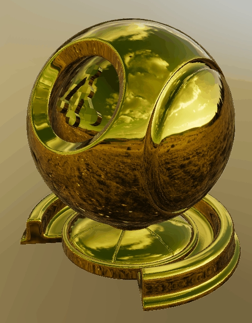
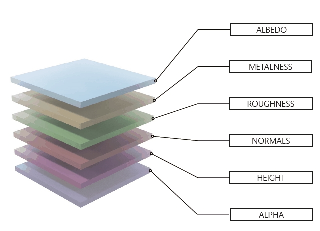
Depence is based on a PBR (Physical Based Rendering) Material concept. Instead of traditional rendering approaches, where artistic values and colors were taken to design a 3D scene, a PBR approach takes more physically correct parameters into account. Especially when it comes to lighting computation, several natural scientific mathematics and rules are used to simulate lighting and materials as realistically as possible.
One important aspect of a PBR pipeline is the definition of materials, which is now not only a color or texture, it is more a physical representation of a surface usually called "PBR Material" or "Substance".
For detailed information about PBR Rendering see:
Create your own PBR Materials:
Source for ready-to-use high-quality PBR Materials:
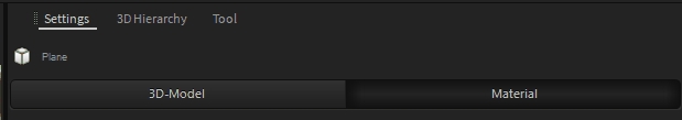
Once an 3D Model is selected, go to the Material Tab in the Settings window, click on Material button.
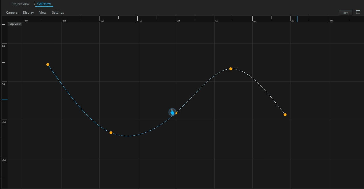
With the free-form spline tool you can draw a spline with your mouse directly within the viewport. Activate the tool in the left toolbar.
Use your left mouse button to add a new point to the spline. Hovering over an existing point moves the point. A Right-click on the spline allows you to insert and delete points.
The spline color indicates the beginning and end of the spline. It starts from blue and changes to white.
To edit an existing spline, select it and run the free-form spline tool.
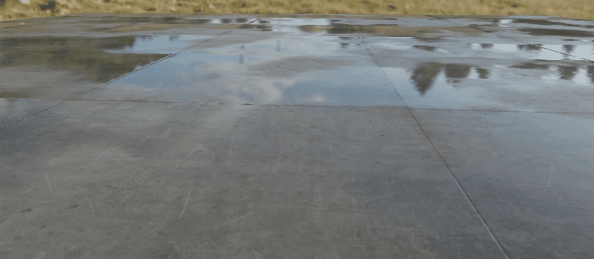
The Reflector extension empowers you to configure reflection settings on a mesh, enabling both planar reflections and bounce lighting effects:
This option enables a reflection plane, which renders the entire scene again from a mirrored perspective and mapped onto the surface. This creates a realistic reflection effect.
The Fresnel value restricts the visibility of the reflection based on the viewing angle relative to the surface.
This value creates a small bias offset to avoid z-fighting and flickering in far distances
The reflection axis is aligned with the origin of the 3D model object. When applying planar reflection, for example, on a cube, the reflection axis can be adjusted using the planar offset.
The planar reflection is blurred based on the material's roughness. This behavior is not always desired and can be adjusted here without modifying the material itself.
With this option, it is possible for a light beam or laser to be reflected. This can be enabled separately for spotlights and lasers.
This option creates an additional light source for each reflector. This can be very performance-intensive!
For bounce lights to work, the shadow quality must be set higher than Low! Also the Cast-Shadow option of the model itself must be active.
Multiple Bounces are only possibe for Lasers (no projections). To enable this, select the Laser-Fixture and look for the child "Laser" object. Here you will find the properties "Max Reflection Bounces" and "Trace Reflections". These define when and how much bounces are supported. Max 4 are allowed.
Bounce lights do not trace shadows.
Objects positioned between the light source and the mirror block the direct light cone but still emit a bounce light.
Multi-bounces are only possible with lasers (beam only)
This only works on flat surfaces
Especially for virtual events we have added a proper chroma-key feature to mask out defined colors from the diffuse channel.
In the PBR Material Settings at the Transparency category, you can find all Chromakey settings.
This Extension can be used on to make non-destructive arrangements on a .
Draw or create a :
Apply the Spline-Arrange Extension (right click on object settings)
Add multiple objects as children under the object: (drag and drop from 3DHierarchy)
Now all child objects of the will always follow the path of the spline according to the extension settings:
The Depence effects particle engine supports multiple particle emitters in a hierarchical order. This makes it possible for particles to be an emitter themselves. Depence comes with a vast library with many - ready to use - default firework shells and effects.
Depence offers two workflows to use and program firework effects. A , which can trigger effects directly by DMX workflow and the more advanced .
The Atmosphere object will automatically be added to your scene along with the terrain object after clicking on Objects > "Create Environment". The atmosphere simulates the sunlight & shadows along with atmospheric scattering depending on the sun's position.
To adjust the sun's position click on the Lighting Icon on the left side of the viewport.
The first control element changes the direction while the second defines the height of the sun.
To get fine sun height control, move your mouse far away after clicking and holding the mouse button on the sun.
The farthest is your cursor, the finest is the control.
The preset buttons on the right can be used to store a specific position. To store a position on a preset button hold your CTRL-Key while clicking on a button.
From the Atmosphere Settings > Custom Map, you can import your own map:
Light settings may be tuned to match your custom map
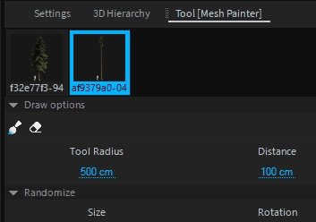
The Terrain Mass Placement Tool allows you to "draw" 3D Models onto the terrain surface. This can be used to easily spread vegetation on the terrain. Activate the tool on the left toolbar.
The tool can hold multiple 3D models, which can be added by drag & drop from the library window.
Each model placed with this tool will automatically snap on the terrain, even if this will be changed later on using the Sculpting Tool.
This material simulates LED video panels with different pixel pitch settings.
The pixels size and pitch can be adjusted to match your screen configuration from Pixels settings:
The screen intensity (unit is ), can be adjusted from Light settings:
The AlphaMask option allows you to create transparent video wall:
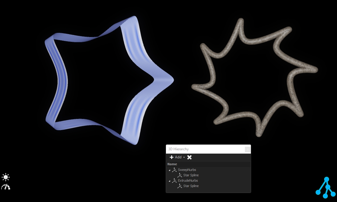
Nurbs are features that generate 3D geometry from .
To add a nurbs feature from the 3D Hierarchy, click on "Add" and select your feature:
All nurbs features require a spline to generate 3D geometry. The must be a child of the nurbs:
Sweep nurbs will create tubes around the :
Its radius can be adjusted through the dimension properties.
Extrude nurbs will extrude the vertically to generate a volume:
Its depth can be adjusted through the dimension properties.
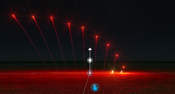
Once you select a firework event on the timeline, the 3D viewport will show you these alignment indicators:
By clicking and moving the white dot, you can change the angle of how the effect will be shot. This will affect all selected events at once.
Holding the CTRL key will create a FAN while SHIFT will make an Even/Odd inverse.
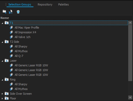
Ordered and organized fixture selection groups are essential for show programming. A Selection Group stores a list of fixtures and the order of how they were selected. Using these groups you always have quick access to all your fixture combinations.
Select your Fixtures within the Project View, Cad-View, or Schematic View.
Navigate to the Selection Groups Window.
Click on Group Selected.
or
Select your Fixtures within the Project View
Drop the fixtures with the drop icon into the selection group view.
Selection Groups are also organized in a tree structure, where you can create folders and change the level by drag & drop.
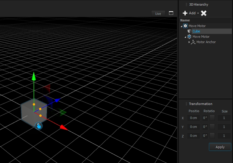
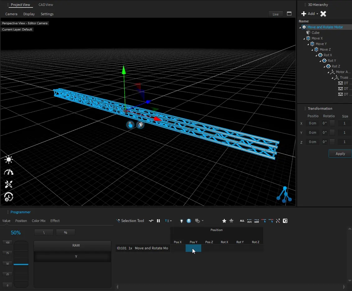
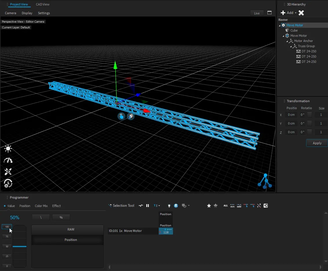
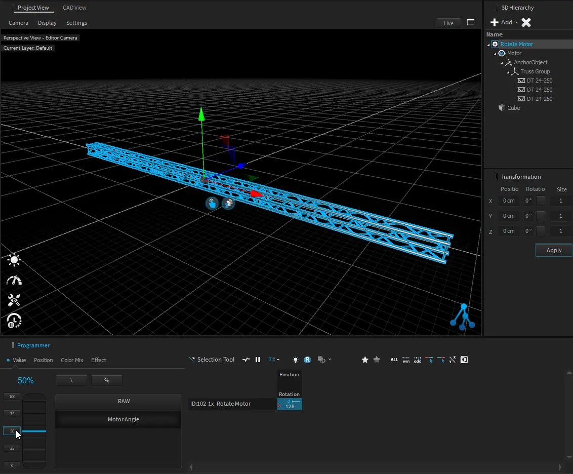
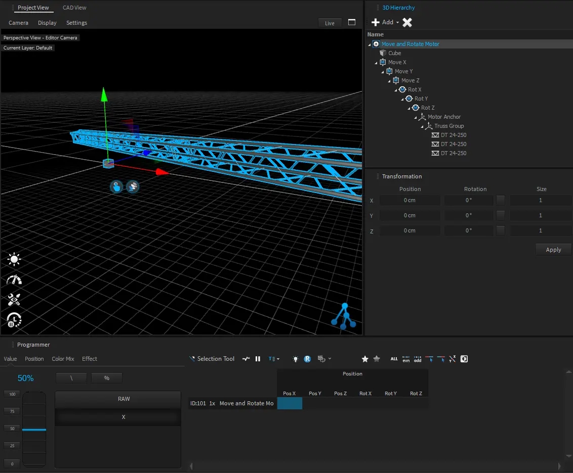
All 3D objects within the project are stored in a hierarchic tree structure called Scene Graph. That means that each object inherits the position, rotation, and scale values from its parent object. All child objects will be always relative to their parent. Therefore, Dynamic objects like Motors also can manipulate their child's relative positions.
A position or rotation in object space means that it might be relative to their parents.
This is the absolute position or rotation in world coordinates.
The hierarchy position of an object can be changed by dragging an object within the 3D Hierarchy window.
By default, the object's World-Space position won’t be changed, because it will calculate a new relative position depending on the new parent Object.
More information about the position is explained within the .
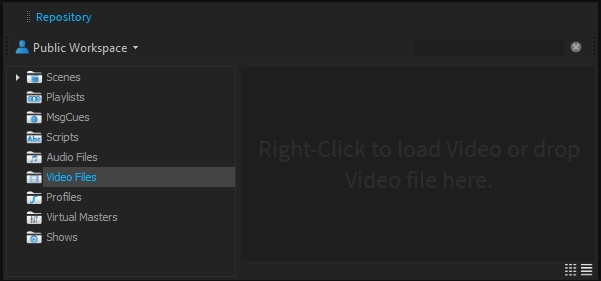
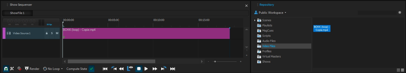
The Media Player source emulates an internal video server to playback videos directly onto the Timeline of a .
Drag and drop a video into the Video Files directory of your workspace, or right-click > new to browse your computer:
Once you have created a , you can add a into the and drag and drop your media into it:
Once a video is played back onto the timeline, it will be visible for all outputs which are assigned to this :
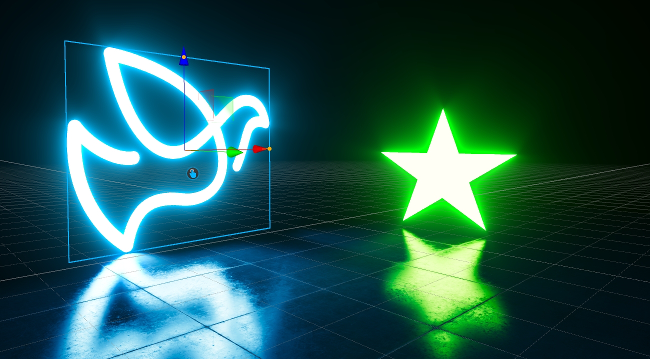
An Arealight emits light from a rectangular plane object with variable sizes. They can be used to simulate any big light sources in a rectangular shape like video walls, screens or even windows in indoor scenes.
Additionally to a diffuse term, the Arealight also calculates a very realistic specular reflection. These reflections are f.e. very important for Video-Screens.
Place a Plane Object in your scene via Menu > Create > 3D-Objects > Plane
Create an Arealight Menu > Create > Lights > Arealight
In the 3D-Hierachy, Drop the Arealight below the Plane object
Arealights only work on Plane-Objects created by Depence. They cannot be used on imported 3D-Models.
The Arealight uses the material applied to the Plane-Object for its lighting calculation. This opens many possibilities.
While the Arealight only works on rectangular plane objects, it is possible to use alpha masking to create other shapes.
Arealights are very GPU heavy! Even if they are black (f.e. due to inactive video source)! Make sure to keep them on separate layers and disable in performance critical scenarios.
Arealights actually don't cast shadows
Starting from version R4, Depence is capable of simulating drone shows. For this purpose, we have defined our own Show Stream file format, which can contain a complete drone show. These shows can be placed and played within the Depence timeline. The following manufacturers already support this format:
Dronisos (www.dronisos.com)
Celestial Drones (www.celestial.show)
VergeAero (www.vergeaero.com)
More are following..
Additionally, it is possible to import drone shows in CSV format, created using SkyBrush () .
3D Hierarchy > Add > Drones > Drone-Swarm
Repository > Sequences > Create a new Show File and open the show
In the Sequencer right click > New Track > Drone Show Track
Right click the Track > Track Settings
In the Settings Window > Choose the correct Drone-Swarm Object
Right click in the track area > Add Events > Add Drone Show
Load a Drone Show File


While Depence is a real-time 3D application it is essential to create and import 3D models, which are optimized for real-time rendering. Otherwise, a lot of performance will be used to just render the models instead of focusing on the main parts like lighting and physics simulation. For a better workflow, follow these guidelines:
Polygon count
Always keeps your 3D-Models as clean as possible to reduce the number of polygons as much as possible. A bigger scene should never exceed 3-4mio polygons.
Make sure you remove unnecessary and nearly invisible parts like small holes, screws, etc.
Merge and optimize your models as much as possible.
Normals
Make sure that surface normals and the winding order of all polygons are correct.
UV Coordinates
If you want to apply textures in Depence later on, all UV coordinates must be correct. Therefore, it can be helpful to always attach a test texture on your meshes, to see if your current mapping is correct.
Texture Dimensions
Always keep texture dimensions as low as necessary. Always note that a 4K texture resolution is not needed, as your viewport and camera projection will limit the final visible resolution. Always consider texture sizes of 1024x1024 or 2048x2048.
Use the power of two texture dimensions. Especially when enabling texture compression, these algorithms won't work correctly, if the texture dimensions are any different.
SHIFT
Locking the translation axis
ALT
Disabling the snap feature


Build Orientation
This will be automatically set, depending on which view (top, left..) you use to build the spline. This is important for arrangement.
Closed
Will close the spline from the first to the last point.
Interpolation
Linear or cubic interpolation mode.
Invert Direction
Inverse the order of points. This also has an effect on arrangements.
Symmetric
This will create a horizontal symmetric form.
Chroma-Key
Activates the chroma-key filter
Chroma-Key Color
The color to be removed
Threshold high
Variable hue threshold
Threshold low
Variable hue threshold
Despill
Removes the green tint
Despill intensity
Amount of despill
Despill luminance
Luminance of despill
Tool Radius
The area to place models.
Distance
The minimum distance between models.
Number
The number of models placed per cycle.
Randomize
Randomization factors of Size & Rotation.
Interval
Interval time in seconds.
Count
Amount of shots.
Random Timing
Randomization in %.
Shape
Arrangement.
Shape Angle
Angle of arrangement.
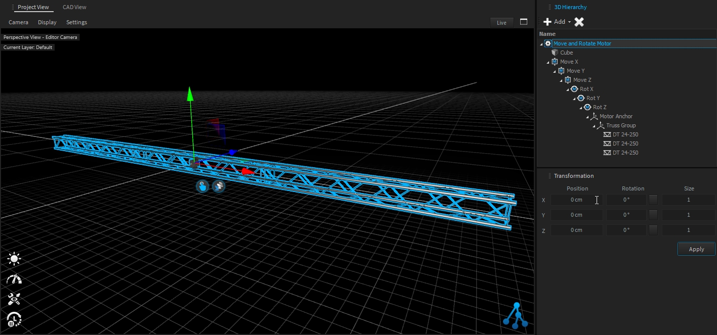
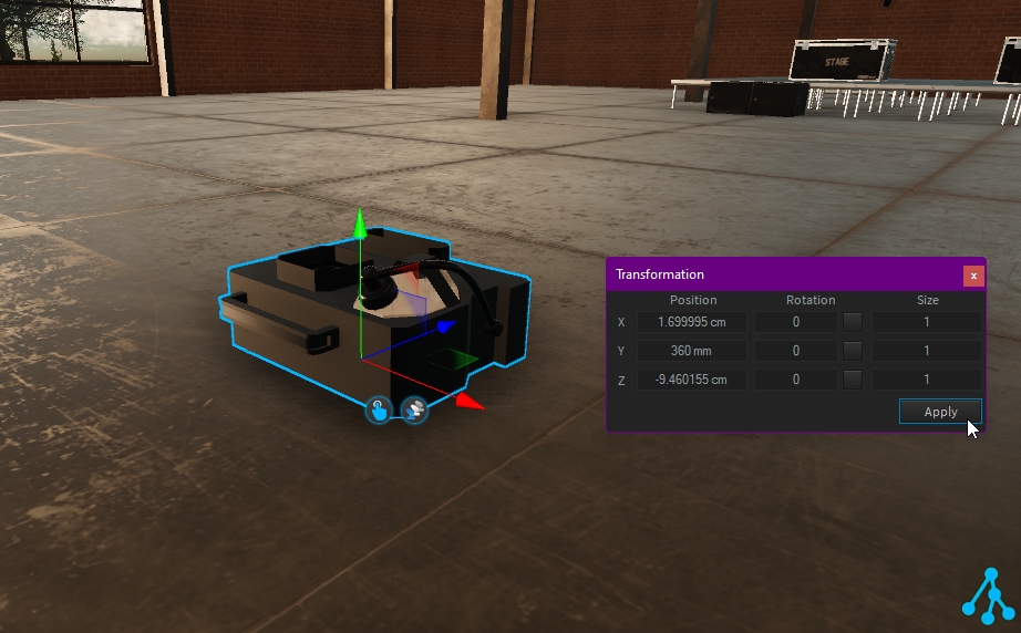
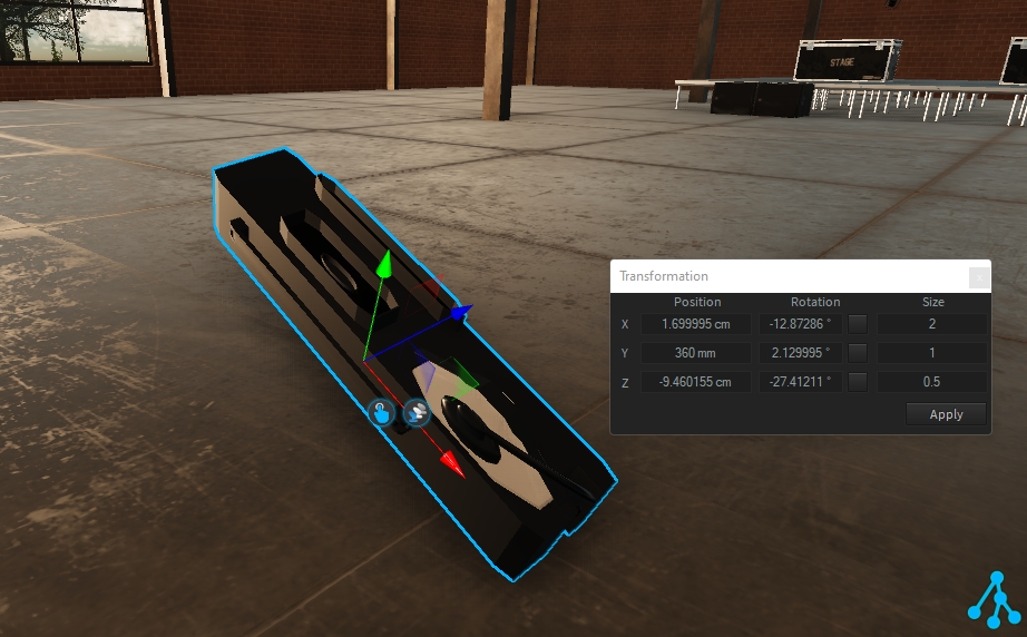
The transformation window displays the current transformation applied on your selection, relative to its parent (if any, else relative to the World Space). This is called Object-Space transformation.
It can be used to position with precision objects (or to correct a position).
The transformation window displays the relative transformation of your selection within its parent. (also known as Object-Space)
This means the transformation window allows you to control the position of the selected object within its parent and not the global transformation from the World Space.
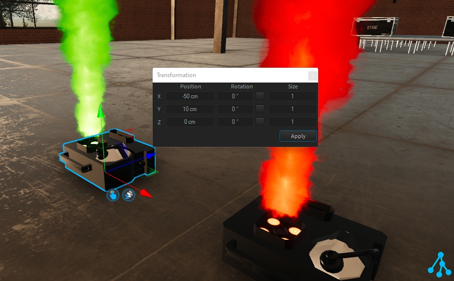
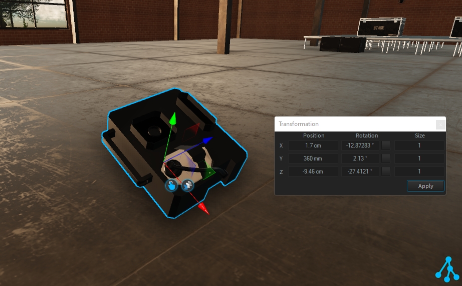
The transformation is made of translation and rotation along 3 axes (X, Y, Z), where each of the axes can be adjusted by entering a value and clicking the "Apply" button.
To adjust the translation position from the transformation window, set the X, Y, or Z position value as needed:
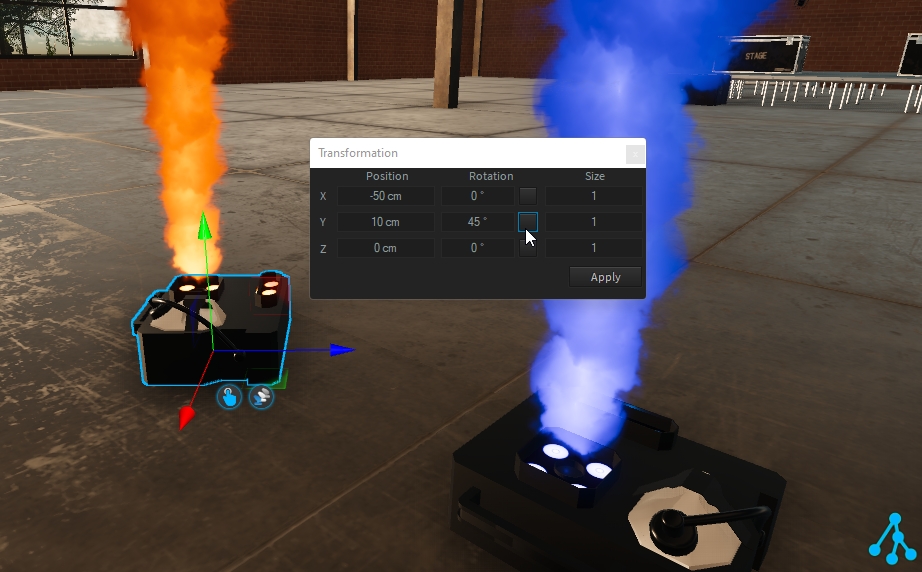
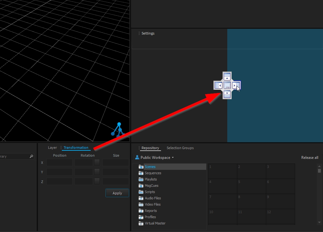
To adjust the rotation angle from the transformation window, you can either:
Set the desired value and press the "Apply" button,
Or click on the square button to apply 45° increment.
Left click to rotate clockwise (CW).
Right click to rotate counterclockwise (CCW).
An additional Size parameter is available to adjust the scale of the selected object (where 2 means 2 times bigger and 0.5 means 2 times smaller).
To reset each type of transformation, double click on "Position", "Rotation" and/or "Size".
Apply the reset by clicking the "Apply" button.
Until you click on the "Apply" button, new transformation values are not applied.
To cancel the update, select another object (from any view or 3D hierarchy).
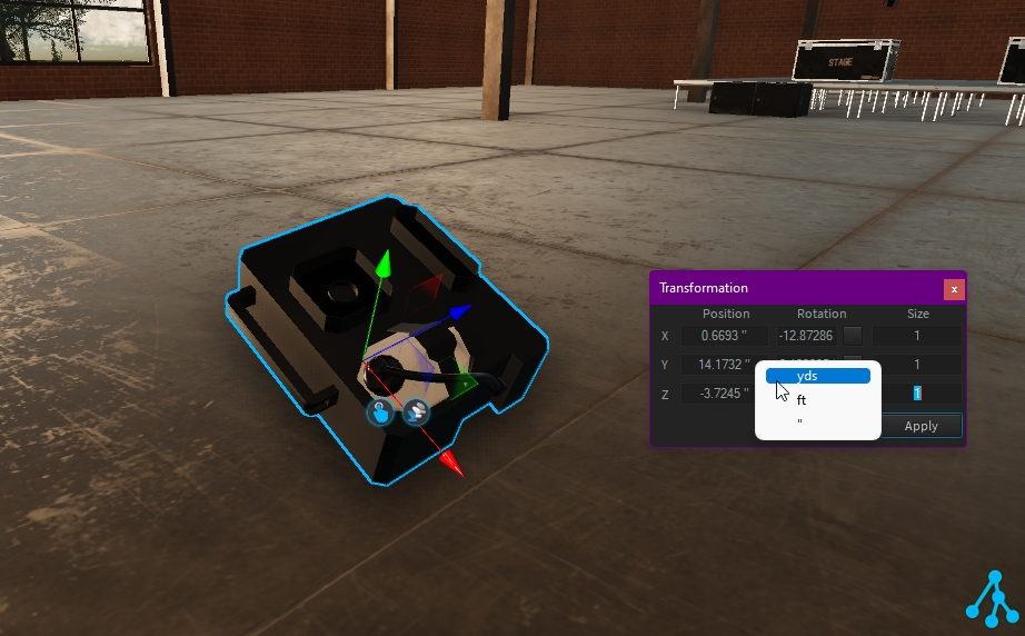
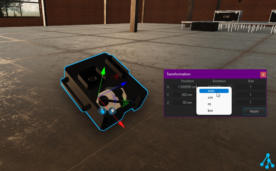
If needed, you can change the current value unit. Right-click on the value to select another unit:
Note: the units displayed depend on your Depence preference.
Most fixtures only have one connector by default, e.g. a nozzle only has a single input connector and a pump has one output connector. Furthermore, some fixtures like valves have one input and one output connector. Once you need to connect e.g. two nozzles to a single pump, you would need a Distributor Fixture in between. A distributor is a virtual fixture, which automatically increments its input and outputs once a connection is established. To add a distributor right-click on the viewport and click on Add Distributor.
Following are three examples of how to use the Distributor:
Several Nozzles on a single Pump
Nozzles with Valves connected to one pump
Several nozzles powered by two pumps
Depence supports different import formats, which are also supported by all major 3D modeling applications like Cinema4D, Autodesk 3DS Max, Maya, etc. Furthermore, it supports the native import of Sketchup files. Please see Supported 3D-Model Import Formats for a list of supported formats.
Go to Objects > Import 3D File in the main menu.
Depending on the file format a settings dialog will appear:
Unfortunately, most 3D file formats do not include information about used measurements, which means that the scale of the 3D models is up to the exporting software and chosen scale factor. Depence uses centimeter as default which means that 1 unit within the 3D file is measured as 1 centimeter in world coordinates. Once your 3D models are scaled or exported differently, you can use this scale factor to change the size accordingly.
Materials - The Importer will sort and merge all meshes by their bound material. This is the most efficient way for real-time rendering and makes material replacement easier. Hierarchy - This will preserve the contained scene graph structure and imports it directly mesh by mesh. This is helpful if you want to keep groups and objects for later editing. However, regarding larger files, this can produce a lot of meshes, which can reduce the system performance drastically.
Depence supports Bone-Animations embedded into FBX (max version 2014) files. Once a file contains animations you need to check this option to force the importer to generate a Bone Animator Object. Please don't use this option on regular models.
Depence supports all major texture formats (Supported Image / Texture Formats) which can be stored in a specific real-time optimized compressed format called DXT. This will reduce the amount of required graphics memory up to four times.
Please note that the compression process can take a while, depending on the size of the textures.
In reality, firework effects will be loaded into "pipes" in several racks placed all over the field. We call these "Firework Position". Each Position Object can hold one or more firework effects ready to shoot.
In the Library, navigate to Firework\Generics\ or in the Main menu Create > Firework > Firework Position
Place one or multiple "Firework-Positions" into your scene:
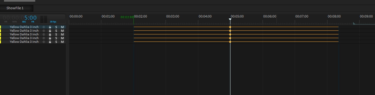
The selection of a specific firework effect usually depends on a current show. For an efficient show programming workflow, every new firework effect will automatically create an event on the current show.
Open or create a new show in your repository and load it into your timeline.
Select one or multiple Firework-Positions in the scene.
Set the show position indicator to f.e. 00:05:00.
Now drag a firework effect from the library on the position objects in the viewport (these will appear yellow).
The Events have been created automatically on the selected show position. They will also get an automatic offset to their explosion moment.
To keep the shows clean and relatively small in data size, each effect can be fired multiple times. You can add more events by clicking the record button on the specific track or just by duplicating an event by holding the CTRL key and moving.
To replace an existing firework effect behind an already existing track, simply drag the new effect from the Library over the track. All shots will remain on their positions.
Make sure you are using the latest software version of Pangolin Beyond. If you have Beyond version 5 or higher, you can output visualization data with any Beyond license. For older versions you need at least Beyond Ultimate and you need to enable your license for the output of visualization data. For this you need to contact your Pangolin partner to obtain a license update. For more questions contact [email protected]
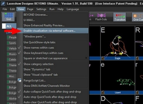
Start Depence and Pangolin Beyond
Within Beyond's Main Menu go to View > "Enable Visualization via external software..."
The small network icon in the status bar indicates an active connection:
In Beyond you can assign a Projection-Zone to a specific laser output that is equal to the laser-source number in Depence. Go to "Settings > Projection-Zones". Here you can change all zone-relating properties. In the "Advanced" tab you can set the Laser Source Output Index for the visualization. In Beyond it's called "Fixture Number".
In the Channel Patch, individual settings of each DMX parameter can be made.
To do this, select the desired fixtures and then select the button labeled "Channel Settings" in the Settings window.
You will now be taken to the Channel Patch dialogue.
In the left list, all DMX parameters of the selected units are displayed in groups. For example, select Intensity here to make settings on the dimmer channel of all selected fixtures.
Now you can make the settings shown in the picture for the selected parameter.
If needed, you can quickly reorganize/adjust the DMX chart of your selected fixture(s).
If the fixture is a known fixture of the market, and you noticed an issue, please report it through our fixture request form!
Select your fixture(s) (same fixture, with same DMX mode)
From the fixture settings: DMX Patching > Channel Settings > Settings...
Click on the button "Adv. Mode Edit..." at the bottom right
From this DMX Settings window, you can:
Delete a DMX Channel by right-clicking on it > Delete
Reorder the DMX Charts using the top arrow and the function Re-Enumerate DMX Channels (to compute the new channel order):
Adjust feature logic to match your fixture: (in this example, Pan Tilt Speed is from 100% speed @0 to 1% of its speed @255)
MVR Import and Export
Depence supports the import of MVR files. You can import fixtures, patch, fixture position, fixture IDs and 3D models with the MVR file. You find the option under File->Import->Import MVR File...
After you have selected the MVR file, a window will open in which you need to match the imported fixture types with fixtures from the Depence library. This is needed, because Depence doesn't use the gdtf file format for the fixtures.
In the matching window, you can drag fixtures from the Library window into the Matching Type column. You need to make sure, that you select the correct DMX mode first, before you drag it into the Matching Window.
After pressing OK, Depence will finish the import.
If your project already contains fixtures or 3D models you should consider the following settings where you can decide how to handle new and already imported objects:
The "Remove none exist.." option only refers to objects who where imported by an ealier version of the MVR file. Objects added manually or by a different MVR file won't be touched.
Depence supports a limited MVR export as well. Depence will currently only export dummy fixtures, because Depence use its own fixture format, which is not compatible with the GDTF file format. Additionally Depence does not export 3D models.
You find the MVR Export function in the main menu under File->Export->Export MVR file...
In the MVR Export window you can select the layers, which you want to export. After pressing Export you can select the export location.
You can import the MVR file into for example your lighting console or a CAD program.
Decals are basically PBR Materials which can be projected directly onto the scene geometry. This can be used to quickly place signs, logos, dirt or other effects without complex UV mapping of 3D models.
A decal object works like an orthographic projector, which affects all objects within its selected area and along the Y+ axis.
Drag the decal from the library and drop it over the object you want:
Using the orange handles, you can scale the decal. Hold SHIFT to scale proportional.
As for any object, you can move/rotate the decal on the surface object:
To create a new decal, add a new decal from menu Create > 3D Objects > Decal
You can save this custom decal in My Library for easy reuse!
Decals are not supported on transparent objects.
By default one event will only fire a single shell. Each firework event has property called Firemode.
Once you select "Stepper" more options will appear.
Shots
Amount of shots per repeat.
Repeats
Repeat all steps again.
Shape
Defines the shot order.
Step Angle
The total angle .
Step Length
Delay between each step (sec).
Mirror
This will invert the order every repeat cycle.
Invert
Inverts the order.
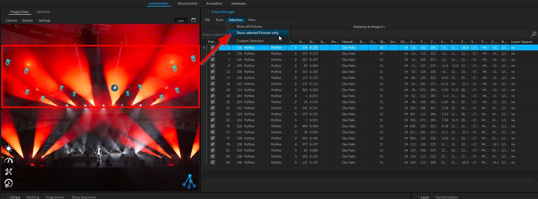
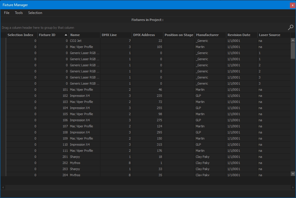
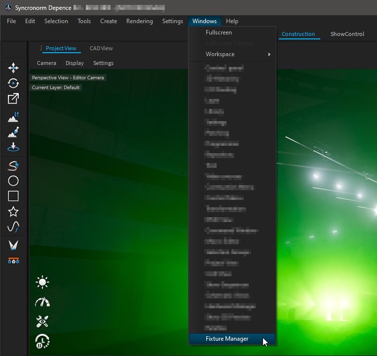
The Fixture Manager window allows managing, viewing, and exporting information about the project's fixtures.
The Fixture Manager window can be accessed through Windows > Fixture Manager.
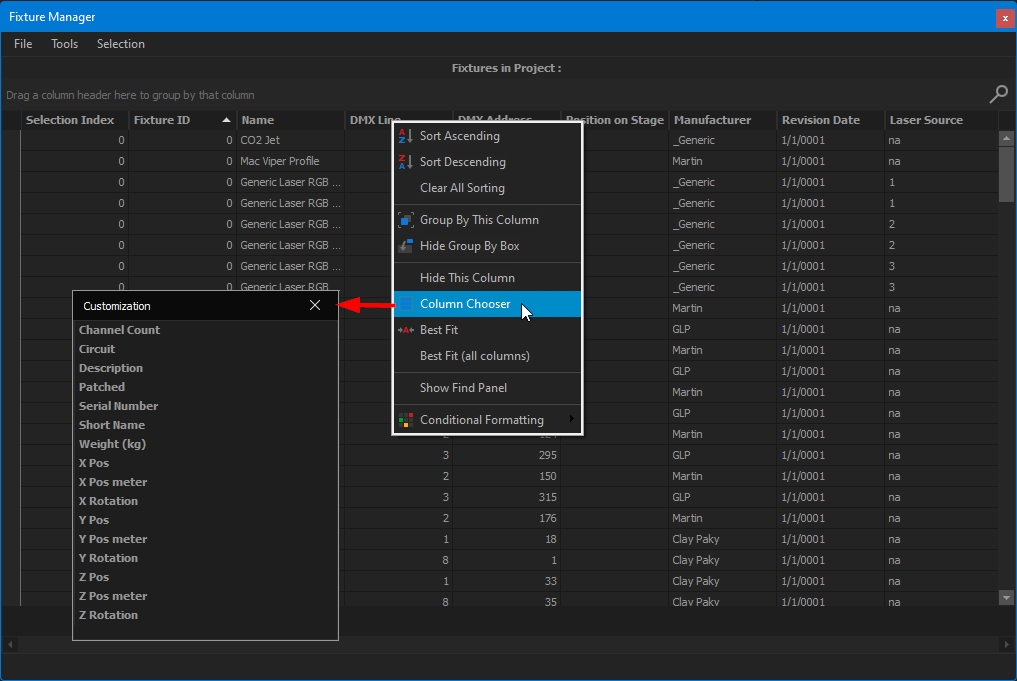
The Fixture Manager window displays the information of the fixture's project inside a table, which can be filtered, sorted, customized, and exported.
If needed, you can restrict the fixtures displayed in the table by using Selection > Show Selected Fixtures Only.
Per default, only a few columns are displayed. Right-click on a column header > Column Chooser to show/hide the desired column.
From the Customization panel, double click or drag and drop the desired column to add it into the table.
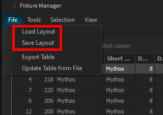
You can save your layout and import it later on, if needed, through the File menu > Load/Save Layout:
The table can be exported as CSV through the File menu > Export Table:
Please note that only shown columns will be exported. If a piece of information is missing, add the column to the table first.
Like its name, you can manage your fixture directly from this window to
Assign Fixture IDs
Change Patch information
Assign Laser Sources
Add a description
Etc. ...
Several tools are available to update your fixtures:
Lighting Fixtures have several adjustable settings available once selected:
Pan and Tilt angle of the fixture can be set through these options (only available on assets with a bracket, not available on moving heads).
It is independent of the Transformation window.
The focus feature (keyboard shortcut F) can be used to easily adjust the asset's focus position.
Moving head lighting fixture has Motor Settings to Invert Pan and/or Invert Tilt.
When accessing the motor setting (Pan/Tilt) of a moving head lighting fixture (from the 3D Hierarchy or from Advanced Settings), their angle can be customized to match your fixture configuration.
Examples:
Pan is set to 180° range on the fixture menu (MaxAngle +90°/ MinAngle -90°)
Pan is set to 630° range on the fixture menu (MaxAngle +315°/ MinAngle -315°)
To improve Depence performance (complex project, low computer specifications, …) it could be interesting to hide the Volumetric Beams generated by the fixture.
Three different options are available:
Always - the volumetric beams are rendered in the live view and when rendering image or video
Render - the volumetric beams are only rendered when rendering image or video.
Never - the volumetric beams are never rendered
If needed, you can artificially increase or decrease the lighting fixture intensity through the Intensity Factor.
If the lighting fixture has several photometrics available, you can change it easily from the Photometric drop-down menu.
When accessing the Light setting of the fixture (from the 3D Hierarchy or from Advanced Settings), you can Edit the Photometrics and adjust them as needed.
Examples:
Fixture color temperature adjustment.
Custom photometric profile for custom diffuser.
Once patched, change the DMX mode of your selected lighting fixture by right-clicking in the project view and selecting the mode through Change Mode menu.
The Depence rendering engine also displays laser beams as well as projections. As input sources, it supports all known major laser control systems like Pangolin Beyond or Laseranimation Sollinger DSP.
The communication between the laser control system and Depence will be established via your local network. This protocol works, when both systems run on the same machine or different machines in your network.
Select one of the available laser fixtures from the library and drag it into the scene. Within the Settings window, you can define a Laser-Source Number for each laser.
This number needs to match the outgoing device number, adjustable in your laser control software.
For the communication between the laser control system and Depence a multicast connection is used. This connection works for multiple receivers without setting up any client IP addresses. Unfortunately, some network routers do not correctly implement multicast. Instead, they use broadcast and send the data to all members of the network, which can interfere with your entire network. Therefore it is recommended to limit the number of active laser sources in the application settings: See Settings > Application Settings > Laser. By default, Depence is listening to 4 sources.
The terrain in Depence offers up to 8 layers to paint any material on. Each layer can be drawn individually. Activate the tool on the left toolbar.
The first layer is a procedural grass layer by default, containing several grass textures, which will be blended automatically depending on the distance to the camera. To add a new layer simply Drag & Drop a material from the library into the tool next to the grass layer.
The selected layer is always active for painting with your mouse, using the left mouse button.
This toolbar defines the current mode of your brush. It can paint, erase or use a brush pattern.
To render big crowds of people Depence has a so called MassCrowd Object, which procedurally places random instances of animated characters.
In the library window, navigate to Models > Peoples > Crowd then select and drag a Crowd-Object into the Scene.
You can select the crowd over this gizmo icon.
The Crowd instances are distributed depending on the current settings. The empty areas can be used to keep specific regions empty. This can be around stages or other scene elements.
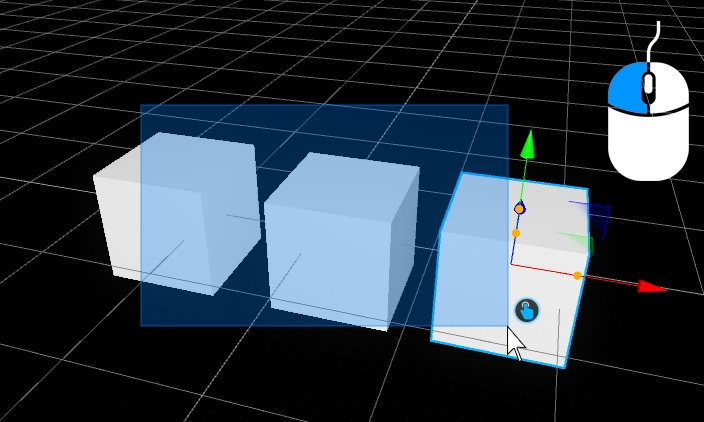
The crowd-object can use the axis-aligned bounding box of any object to cull out the instances.
In the 3D-Hierachy window > Add > 3D-Object > Cube
Place and size the cube to define the empty area (note: the cube shall be in clash with the floor to be detected as NoGo area)
Select the Crowd Object and in its Settings click on "Empty Areas ..."
Drag the Cube object from the 3D-Hierarchy in the Dialog box
Select the Cube again and set the Visible property to false
After updating the Cube's transformation, click on Crowd settings "Refresh" button to refresh the empty area
The focus object allows you to define another object in the scene as a focus point, where all crowd instances will look at. The focus object can be any object type, f.e. a Generic > Group Object
The DMX-Matrix feature creates a UV-mappable Matrix texture based on DMX values. This feature can be used to simulate thousands of LED fixtures without the performance overhead of individual fixtures because it directly reads DMX values from the internal buffer.
To add the DMX-Matrix feature on a model, access its Material settings, and click on the "..." button:
Close the window to validate your settings.
The DMX-Matrix is material based. To make it emissive (visible in the dark), don't forget to raie the Emissive factor (maximum value is 500%):
Now your material is ready to be used. You can patch the DMX Matrix fixture from the fixture library:
The DMX Matrix fixture has the same mode as the DMX Matrix Texture, select the one you have set.
You need to patch as many DMX Matrix fixtures as your DMX Matrix Texture has (Columns x Rows)
Note: - DMX Matrix fixture only controls 1 pixel at a time. - Their position in world space is not important, they are not represented in 3D.
To keep your project 3D Hierarchy as clean as possible, you can all your DMX Matrix fixtures:
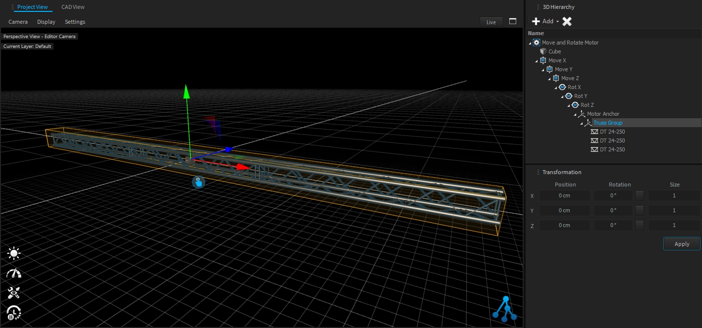
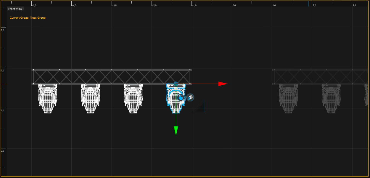
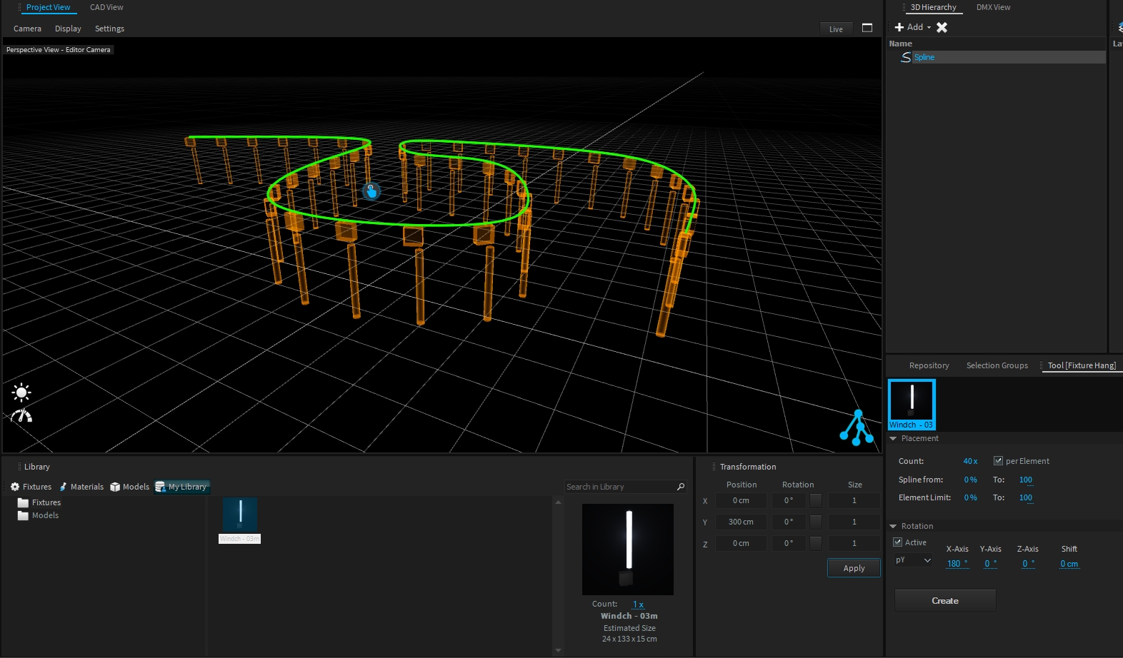
The Fixture Hang tool allows you to add multiple fixture types directly on truss pipes or splines within a single action.
Note: Fixture Hang Tool only works with native Depence Trusses & .
Select pipes or splines with your left mouse button (hold CTRL for multi-selection).
Drop your fixtures from the library into the Hang Tool.
To create and auto-patch the fixtures click on Create. If you hang fixtures on trusses, the fixtures will automatically be grouped with the truss group.
There are hundreds of different component combinations possible, especially in fountain technology. You can connect different types of nozzles with different types of moving fixtures and lights. With Depence it is now possible to simply "snap" fixtures onto other fixtures. This makes it easy to test different permutations of water effects.
First add an Oase Multi Direction Drive to the scene via Drag & Drop.
Make sure the fixture is still selected.
Now, navigate to the nozzles and select the "Comet Prec 20-20" nozzle (which is intended to be used with this type of MDD).
Drag this nozzle over the existing MDD and over the appearing green anchor point.
Once you have dropped the nozzle on the fixture, it will be mechanically connected to the MDD.
Now you can repeat to "mount" the optional LED-Module to the nozzle. This option can be found at Illumination > LED Techn. > LED Module II.
In the 3D-Hierarchy you can see how the fixtures are now children of each other:


General
CTRL+N
New Project
CTRL+S
Save Project
CTRL+ALT+SHIFT+O
Open Project
CTRL+Z
Undo
CTRL+SHIFT+Z
Redo
CTRL+U
Selection Undo
CTRL+SHIFT+U
Selection Redo
CTRL+DEL
Delete Objects
CTRL+D
Duplicate Objects
CTRL+G
Group Objects
CTRL+SHIFT+G
Ungroup
CTRL+P
Autopatch selected Fixtures
CTRL+SHIFT+D
Auto Connect Dependencies
ALT+SHIFT+D
Disconnect Dependencies
3D Editor
CTRL+(F1...F12)
Store current Camera Position to F-Key
F1...F12
Jump to saved Camera Position
CTRL+Move
Duplicate selection
CTRL+SHIFT+Click
Directly select the last object in hierarchy
O
Zoom Camera to selection
CTRL+E, E
Move Tool
CTRL+R, R
Rotate Tool
CTRL+T, T
Scale Tool
ESC
Exit Tool or Group and deselect
CTRL+W, W
Toggle Worldspace/Objectspace
L
Toggle Live-Mode
ALT+Move
Move object without Snapping
SHIFT+Move
Lock on Axis
F+Click
Focus selected fixtures & Camera Objects to the mouse position
Show Sequencer
ALT+Mouse Wheel
Zoom
Mouse Wheel
Scrolling up & down
SHIFT+Mouse Wheel
Change Track Sizes
Spacebar or Enter
Play / Stop
NumPad 0
Jump to Sequence Start
NumPad 1
Jump to Loop Region - Left Locator
CTRL+L
Toggle Loop Region On / Off
CTRL+Move EventBlock
Duplicate selected Blocks and move to a new Position
Middle Mouse Button + Move left / right
Move EventBlock Area
The tail is a particle emitter who emits particles in every frame to create characteristic tail effects. A Tail can be a child of a Shell or Star object.
Firework Color
Pre-defined colors.
Custom Color
Once the Firework Color is set to Custom, a RGB defined color can be used.
Lifetime
Total lifetime in seconds.
Lifetime Random
Randomization of the Lifetime in %.
Enabled
Enabled the emitter.
Emit Count
Particles per Frame.
Velocity
Output velocity in m/sec.
Spray
Random output direction in °.
Mass
a factor on gravity.
Air Resistance
Air resistance factor.
Radius
Particle Radius (WS).
Min Pixel Radius
Minimum Size of the particle in pixel.
Fade In
How long the particle fades in (% on lifetime).
Fade Out
How long the particle fades out (% on lifetime).
Blink Frequency
Blink/Strobe frequency in Hz.
Blink Amplitude
Blink/Strobe Amplitude in %.
Stars are emitting bright particles in different colors and shapes.
Firework Color
Pre-defined colors.
Custom Color
Once the Firework Color is set to Custom, a RGB defined color can be used.
Lifetime
Total lifetime in seconds.
Lifetime Random
Randomization of the Lifetime in %.
Enabled
Enabled the emitter.
Explosion Delay
Explosion in sec after parent was fired.
Explosion Delay Random
Randomization of the delay in %.
Count
Amount of stars .
Explosion Distribution
Sphere, Hemisphere, Ring.
Energy
Explosion Radius in meter.
Radius
Size (WS) of the Particle.
Min Pixel Size
Minimum Size of the particle in pixel.
Fade In
How long the particle fades in (% on lifetime).
Fade Out
How long the particle fades out (% on lifetime).
Blink Frequency
Blink/Strobe frequency in Hz.
Blink Amplitude
Blink/Strobe Amplitude in %.
Air Resistance
represents air resistance (a factor of the res. of a unit sphere at cw=1 and 1kg). ⚠️ too high resistance can cause the particle to not emit, because it would never reach the defined height!
Sound
On/Off.
Sound Energy
0..1 value for the sound engine to select different sounds depending on the energy.
A Crackle can be a child of a Stars object, to create a crackling 3nd explosion on each Star.
Firework Color
Pre-defined colors.
Custom Color
Once the Firework Color is set to Custom, a RGB defined color can be used.
Lifetime
Total lifetime in seconds.
Lifetime Random
Randomization of the Lifetime in %.
Enabled
Enabled the emitter.
Explosion Delay
Explosion in sec after the parent was fired.
Explosion Delay Random
Randomization of the delay in %.
Emit Count
Particles per Frame.
Velocity
Output velocity in m/sec.
Air Resistance
Air resistance factor.
Radius
Particle Radius (WS).
Min Pixel Radius
Minimum Size of the particle in pixel.
Fade In
How long the particle fades in (% on lifetime).
Fade Out
How long the particle fades out (% on lifetime).
Blink Frequency
Blink/Strobe frequency in Hz.
Blink Amplitude
Blink/Strobe Amplitude in %.
Sound
On/Off.
A Shell object represents a shell-bomb, which emits a single or multiple particles which can carry further emitters f.e. Stars or Tails.
Firework Color
Pre-defined colors.
Custom Color
Once the Firework Color is set to Custom, a RGB defined color can be used.
Lifetime
Total lifetime in seconds.
Lifetime Random
Randomization of the Lifetime in %.
Enabled
Enabled the emitter.
Height
Maximum Height in meters.
Count
Amount of shells to emit.
Random Direction
Random direction on every shot.
Comet
Visible Comet particle.
Comet Size
Size (WS) of the Comet Particle.
MinPixelSize
Minimum Size of the particle in pixel.
Sound Energy
0..1 value for the sound engine to select different sounds depending on the energy.
Sound
On/Off.
Air Resistance
represents air resistance (a factor of the res. of a unit sphere at cw=1 and 1kg). ⚠️ too high resistance can cause the particle to not emit, because it would never reach the defined height!
Random Velocity
Randomization on the velocity in %.
Fade In
How long the particel fades in (% on lifetime).
Fade Out
How long the particle fades out (% on lifetime).
Blink Frequency
Blink/Strobe frequency in Hz.
Blink Amplitude
Blink/Strobe Amplitude in %.
All child objects will be carried by the shell and will be ignited.
Laser Source
Input Device Number.
Projection Intensity Factor
Factor to reduce or rise the intensity for projection only.
Projection Line Width
Change the line width on projections (only once per Source).
Total Output Power
Affects projection and beam intensity.
Invert X & Y
Inverts the output on both axes.
Scanning Angle
Defines the maximum scanning angle.
Tool Radius
Changes the radius of the tool itself.
Strength
Defines the intensity and power of each draw cycle.
Hardness
Defines the hardness/softness of the edges of the brush.
Color Mix
This will multiply the diffuse texture color with a given color.
Grass Layer
Active on first grass-layer by default. Only one layer can be grass.
Roughness
A roughness multiplier on the material.
Scale
Scales the UV mapping for this layer.
Min/Max Angle
Limits the visibility depending on the surface normal. This can be used on a filled layer e.g. to show stones/cliffs on steep angles.
Min/Max Height
Limits the visibility depending on the height.
Texture Diffuse
Can load a custom texture for the Diffuse Channel. Automatically filled by the dropped material.
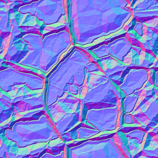
Texture Normal
Can load a custom texture for the Normal Channel. Automatically filled by the dropped material.
Columns
Number of Pixel per column
Rows
Number of Pixel per row
Channel Layout
DMX Channel layout as: - RGB: Red Green Blue - GRB: Green Red Blue - RGBW: Red Green Blue White - WRGB: White Red Green Blue - RGB16: Red Green Blue in 16bit - GRB16: Green Red Blue in 16bit - RGBW16: Red Green Blue White in 16bit - WRGB16: White Red Green Blue in 16bit
Start Address
DMX start address for the given universe
Universe
DMX Universe to start to patch
Count
Total Amount of fixtures (or per element).
Spline From/To
Limits the arrangement (if not per element).
Element Limit
Limits the arrangement per element (useful to keep fixtures on trusses).
Rotation
Rotation offset in addition to current spline rotation.
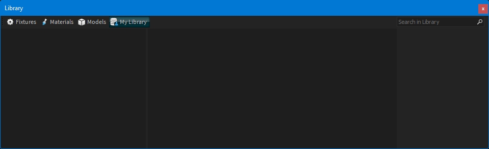
My Library is a tab of the Library window dedicated to you, where you can store fixtures or models.
This library is shared with all your projects.
To organize your personal library, you can create/delete/rename folders (right-click on the left panel to display the dropdown menu):
Important:
You cannot store objects in the My Library root folder, at least one folder must exist to be able to store an object.
To store a fixture or a model within My Library, this object should be already present in the Scene Graph.
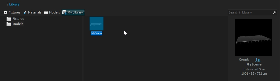
Select the folder where to store it, then select the object to store and drag and drop it into the right panel of My Library:
Select the folder where to store your object.
Select your object selection (use the hand icon ).
Drag and drop your selection in the right panel of My Library.
EnterCongratulations! You have added your first model to My library!
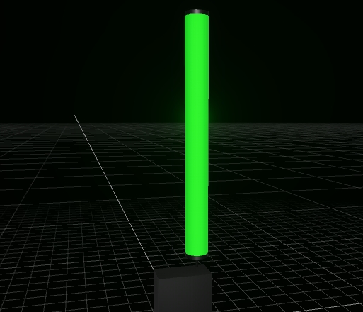
For modular fixtures (fountains, or motorized fixtures), it can be useful to store these inside My Library to allow easy placement later on.
The way to store them is the same as for an object.
Example of a motorized fixture:
From now on, you can use your assembled fixture with the Fixture Hang Tool:
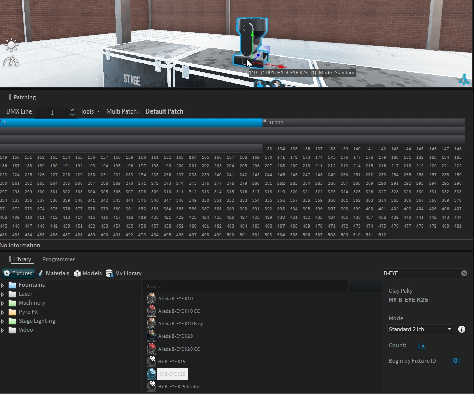
In contemporary lighting setups, lighting consoles are increasingly controlling fewer pixel LEDs, while media servers are becoming the norm. To accommodate this shift, lighting fixture manufacturers have begun splitting DMX control, allowing for physical separation of control across different DMX universes. This trend is becoming more prevalent as fixtures often require control spread across multiple DMX universes.
A lighting fixture with multiple DMX addresses (pixel engine) typically has independent DMX modes for each part.
For example, the Clay Paky HY B-EYE K25 consists of two main parts:
Main Fixture: Controls aspects like position, master intensity, and beam.
DMX Modes: Standard, Shapes
Pixel Engine: Provides independent control over LED pixels.
DMX Modes: RGB, RGBW
When patching a fixture with multiple DMX addresses, all parts of the fixture will be automatically patched, with the first DMX mode used by default for each sub-part.
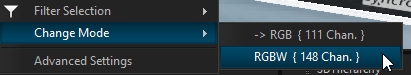
The fixture sub-part, or pixel engine, functions like a separate fixture.
To change the DMX mode, select the fixture sub-part (pixel engine) and change the DMX mode from the "Change Mode" option:
Once selected, patch the fixture sub-part (pixel engine) as needed by drag and dropping the hand icon from the project view:
From the Patching window, you can unpatch the sub-part (pixel engine) if necessary.
For certain fixtures where the Pixel Engine is deeply integrated with the Main Fixture for technical reasons, additional DMX modes are created without the Pixel Engine.
These modes are labeled with the suffix "Without Pixel Engines" and should be used when the Pixel Engines are unpatched to ensure the fixture operates correctly.
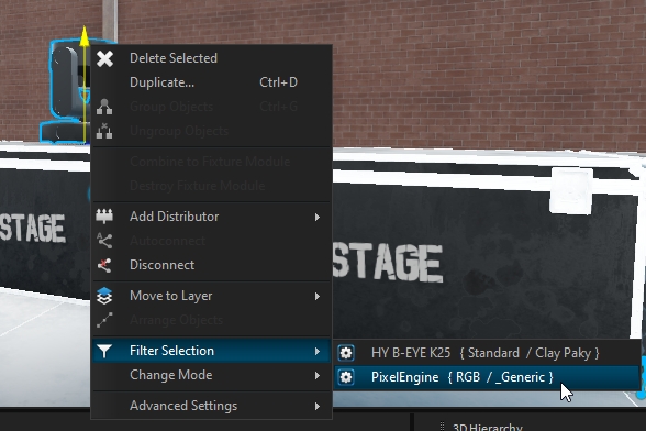
Managing multiple fixtures with one or more pixel engines can be complex, but using the filter selection function and the Fixture Manager window simplifies the process.
Use this function to select all pixel engines under your fixture simultaneously:
Change the DMX mode for all selected pixel engines through the Change Mode function:
After setting the DMX modes, reorder the patch to ensure there are no gaps and that it meets your requirements, you can do it manually, or using the Fixture Manager
Open Fixture Manager: Access the Fixture Manager window to select all your fixtures and their associated pixel engines.
Filter and Sort: Use the filter option on any column to help sort and organize your selection.
Repatch Fixtures: Drag the hand icon from the project view and drop it into your patch. The order of selection will determine the patch order, so ensure it is in the desired sequence.
Depence comes with a hierarchical layer structure, which can have layers being children of other layers. Especially for bigger projects, layers are required to temporarily hide or lock parts of your scene.
Click on Add new Layer button to create a new layer. The Edit Layer window opens:
To select the layer color you want, maintain a left-click and in the color rectangle and select your color:
To find the layer associated to an object, select your object, right-click and choose Move to Layer, the current selected layer is where the object is linked:
Multi-selection is not supported to display the layer
To move an object to a different layer, select the object(s), right-click and choose Move to Layer:
A second way is to right-click on the target layer and choose Move selected, which will put all selected objects into this layer.
Select the layer to delete, and click on Delete selected Layer:
Each layer has 5 parameters:
Color: Layer color (defined at creation)
Name: Layer name (defined at creation)
A - Active: Current active layer
V - Visible: Visibility of the layer (children layer inherit from it)
S - Solo: Only Solo layer is visible (children layer inherit from it)
L - Lock: Allow or lock modification of the layer (children layer inherit from it)
Layer Color & Name can be changed at any time by double clicking on the layer to be updated. The Edit Layer window will appear (see ).
The layer color can be helpful to organize e.g. fixture or object types.
The CAD view will also draw fixtures in layer color:
Once you add a new object to your scene it will be automatically linked to the currently active layer:
To change the current active layer, click in the A column of the layer you want.
The visible parameter can be used to quickly hide layer(s) we don't need:
The Solo parameter can be used to "Solo" a layer.
It is useful to restrict the visibility of all layers except the solo one:
When a layer is locked it can not be selected or either modified.
Depence comes with a fully integrated timeline-based show control system. The seamless integration of Visualization and Show Control offers tons of new workflows.
This Extension controls the visibility of its object. This can be used to make multiple LOD (Level-Of-Detail) Models while making its visibility depending on the distance to the camera or to disable certain parts of a scene depending on a current Quality setting.
Software and Asset library updates can only be detected and applied while your computer is connected to the Internet.
If an update is available, a notification will be displayed on the top right of the Depence homepage:
Simply click the update you would like to run, and follow the instructions.
This tool will create a formular spline. Select the Formular Spline tool on the left toolbar.
Click with your left mouse button on the position where the spline should be centered.
Depence will create the Spline on this position.
X(t) = (100 * Cos(t * PI)) / t Y(t) = 0.0 Z(t) = (100 * Sin(t*PI)) / t t-Min = 1.0 t-Max = 5.0 Samples = 50
X(t) = (90 +30) * Cos(t * PI) - 40 * Cos(((90 + 30) / 30) * t * PI) Y(t) = 0.0 Z(t) = (90 + 30) * Sin(t * PI) - 40 * Sin(((90 + 30) / 30) * t * PI) t-Min = 1.0 t-Max = 3.0 Samples = 65
X(t) = 100 * t Y(t) = 0.0 Z(t) = if(t % 1.0 > 0.5, 0.0, 100.0) t-Min = 0.0 t-Max = 5.0 Samples = 80
To manually connect fixtures with Dependencies please pay attention to the following rule: Connect Passive Fixture > to > Active Fixture.
Select the passive fixture (e.g. nozzle).
Click and hold your left mouse button on the Connect icon next to the passive fixture.
Drag your mouse over the active fixture until it gets highlighted.
Releasing your mouse button will connect the fixtures.

x(t), y(t), z(t)
Equations on (t) for each Axis.
t-Min, t-Max
Specified the definition range.
Samples
Amount of interpolation points.
+ - * / ( ) %
Basic mathematical operators.
Abs(a)
Returns the absolute value of a specified number.
Acos(a)
Returns the angle whose cosine is the specified number.
Asin(a)
Returns the angle whose sine is the specified number.
Atan(a)
Returns the angle whose tangent is the specified number.
Ceiling(a)
Returns the smallest integer greater or equal to the specified number.
Cos(a)
Returns the cosine of the specified angle.
Exp(a)
Returns e raised to the specified power.
Floor(a)
Returns the largest integer less than or equal to the specified number.
Log(a, b)
Returns the logarithm of the specified number.
Log10(a)
Returns the base 10 logarithm of a specified number.
Max(a, b)
Returns the larger of two specified numbers.
Min(a, b)
Returns the smaller of two numbers.
Pow(a, b)
Returns a specified number raised to the specified power.
Round(a)
Rounds a value to the nearest integer or specified number of decimal places.
Sign(a)
Returns a value indicating the sign of a number.
Sin(a)
Returns the sine of the specified angle.
Sqrt(a)
Returns the square root of a specified number.
Tan(a)
Returns the tangent of the specified angle.
Truncate(a)
Calculates the integral part of a number.
if(condition, true-part, false-part)
Returns a value based on a condition Example: if(t > 0, 50, -50)
Color Deep
Color for deep water.
Color Shallow
Color for shallow water.
UV-Mapping
UV or Box Mapping.
Tile Size
Size per Tile.
Turbidity
Change the turbidity of the water.
Animation Speed
Changes the speed of normal animation.
Bump Scale
Changes the wave height.
Normal Texture
Custom Waves Normal Map.
Scale X/Y
Scales the Normal Map.


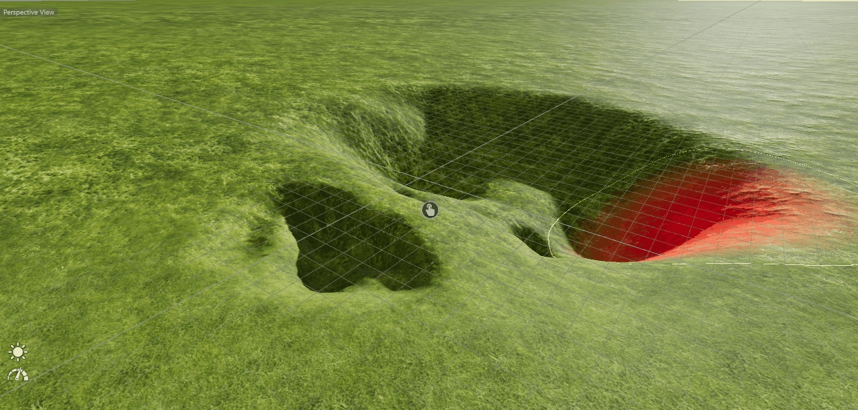
The Terrain Sculpting Tool allows you to manipulate the terrain surface with your mouse by simply drawing on it. Activate the Tool on the left toolbar.
The Tool offers 5 different modes:
This tool will pull down the terrain depending on the options and limits.
This tool will rise the terrain depending on the options and limits.
This tool will randomly uneven the terrain depending on the options and limits.
This tool will smooth all uneven ground in a given radius depending on the options and limits.
This tool will pick the height of the position you click and create a flat area on this height.
Heightmaps are grayscale images defining a terrain structure by its white value where black is the lowest and white the highest point on the map. Various heightmaps are available on the web and can also be exported from programs like Google Earth. It is recommended to use power of two images sized like (1024x1024, 2048x2048..).
This tool will draw a rectangular spline. Select the Rectangular Spline tool on the left toolbar.
Click and hold your left mouse button for the first point.
Move your mouse to extend the rectangle.
Release the mouse button to create the spline.
Hold CTRL to keep the center on the first position you have clicked. Hold SHIFT to lock width and height to create a square.
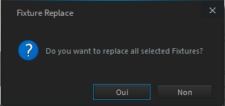
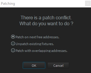
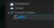
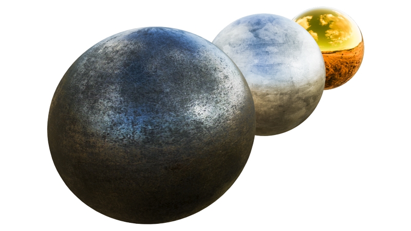
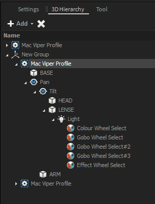
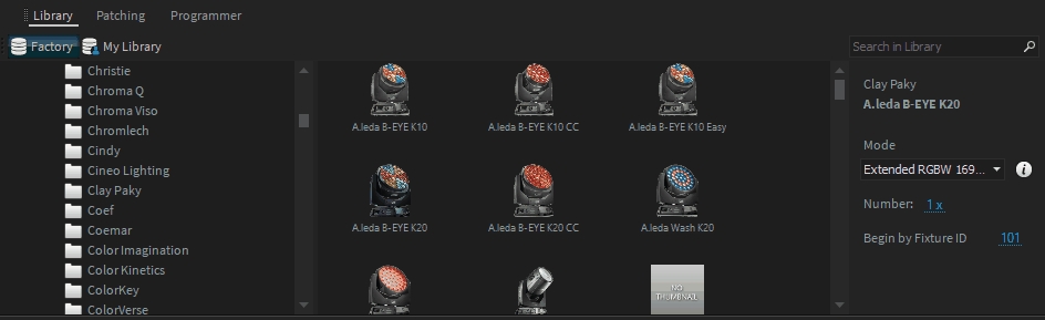


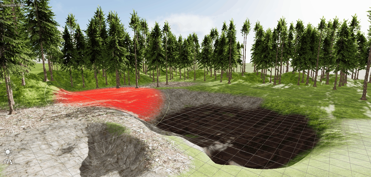
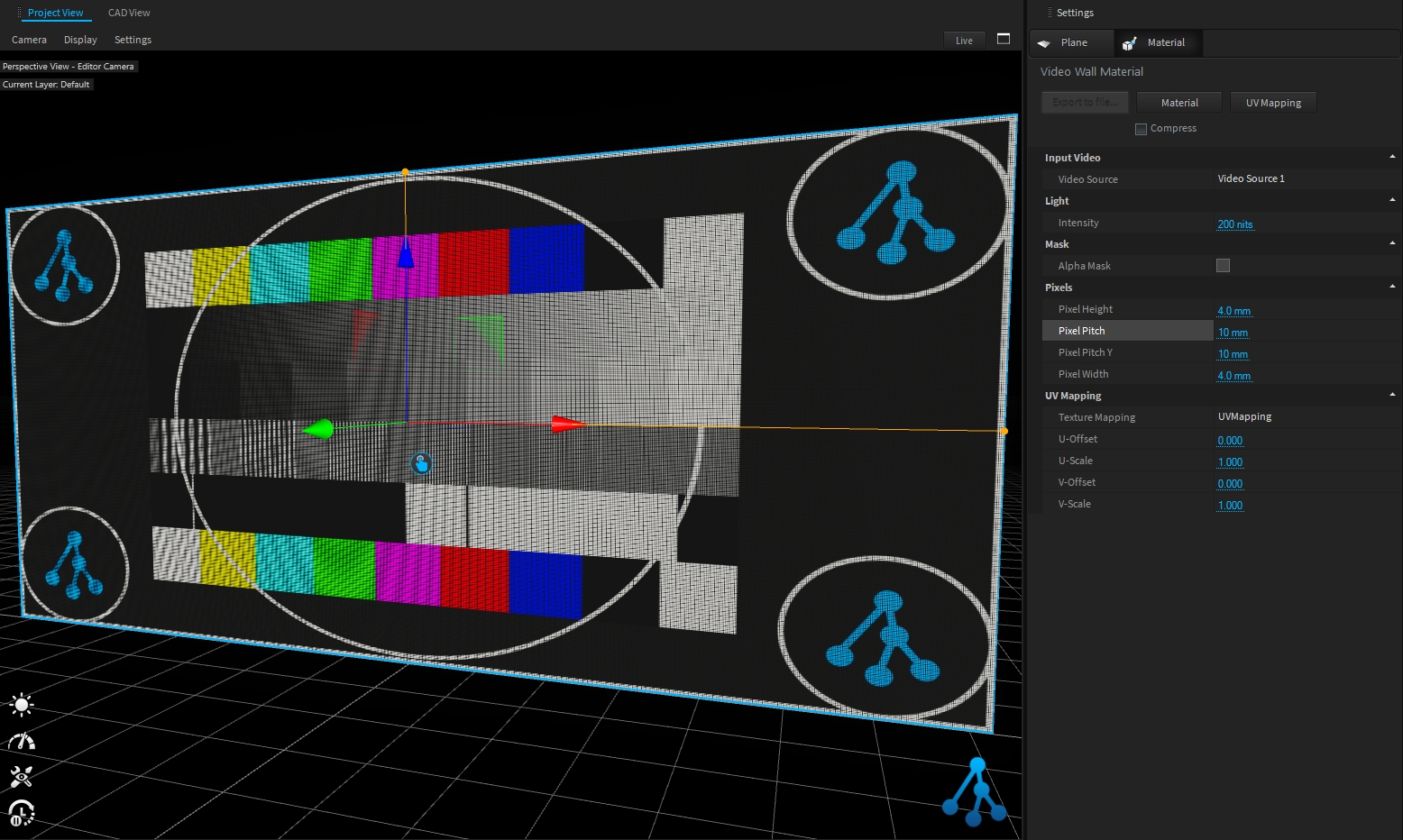
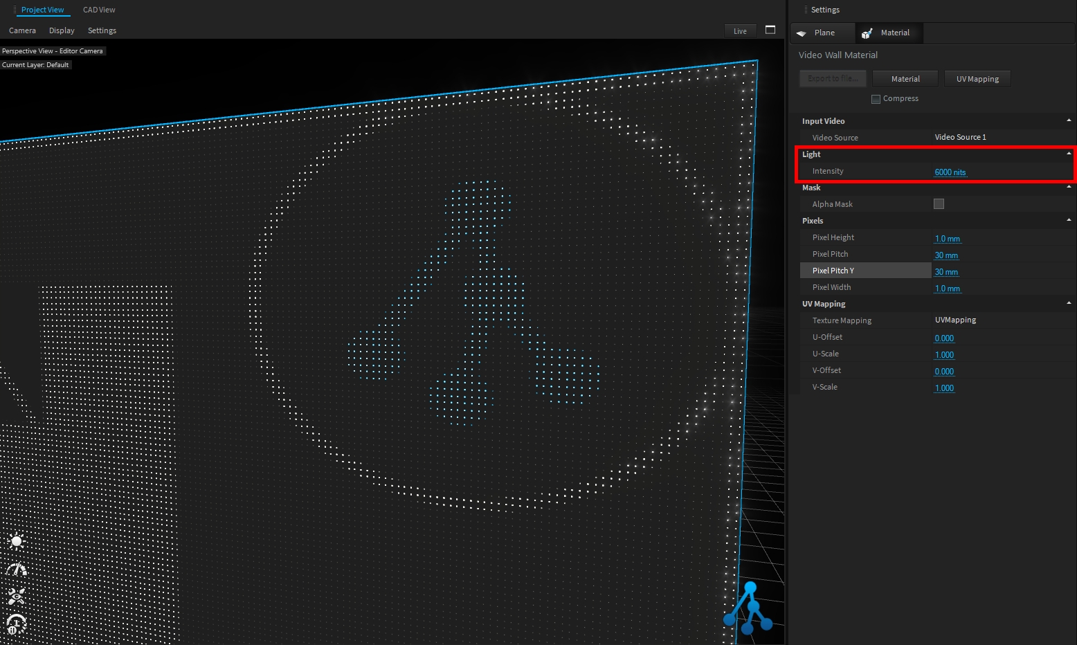
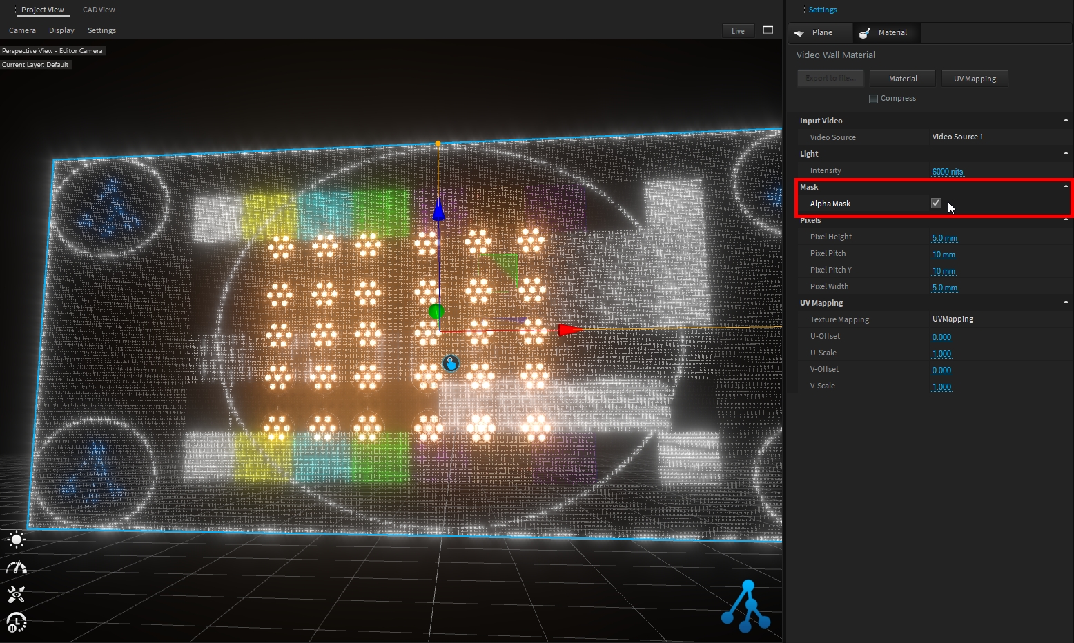
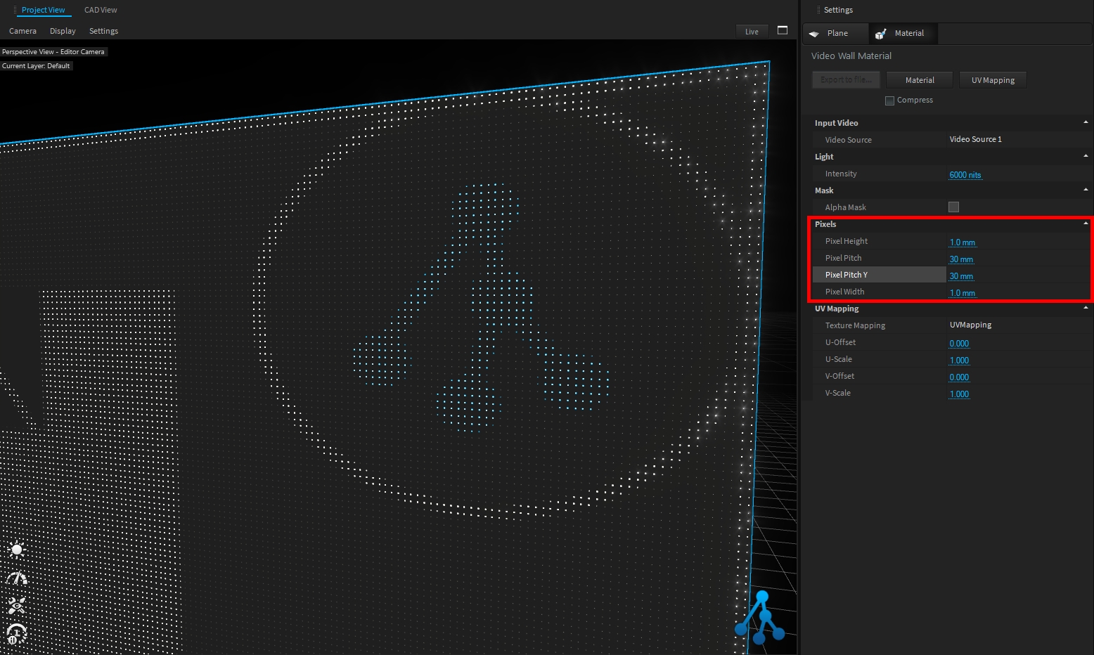
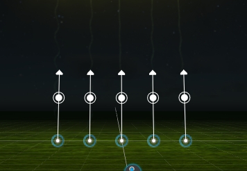
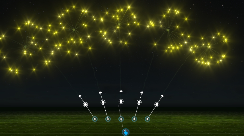
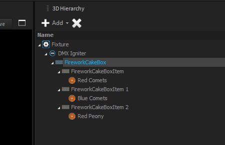
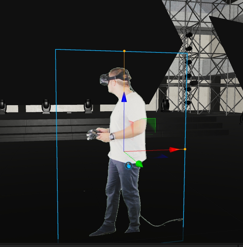
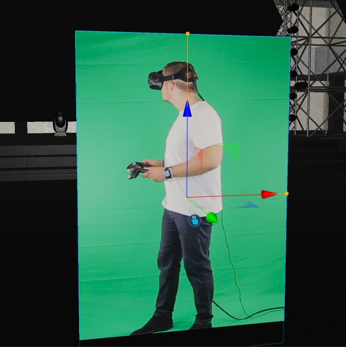
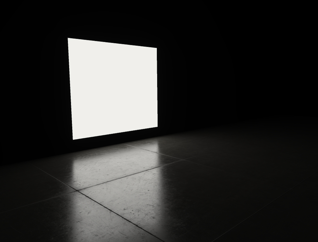
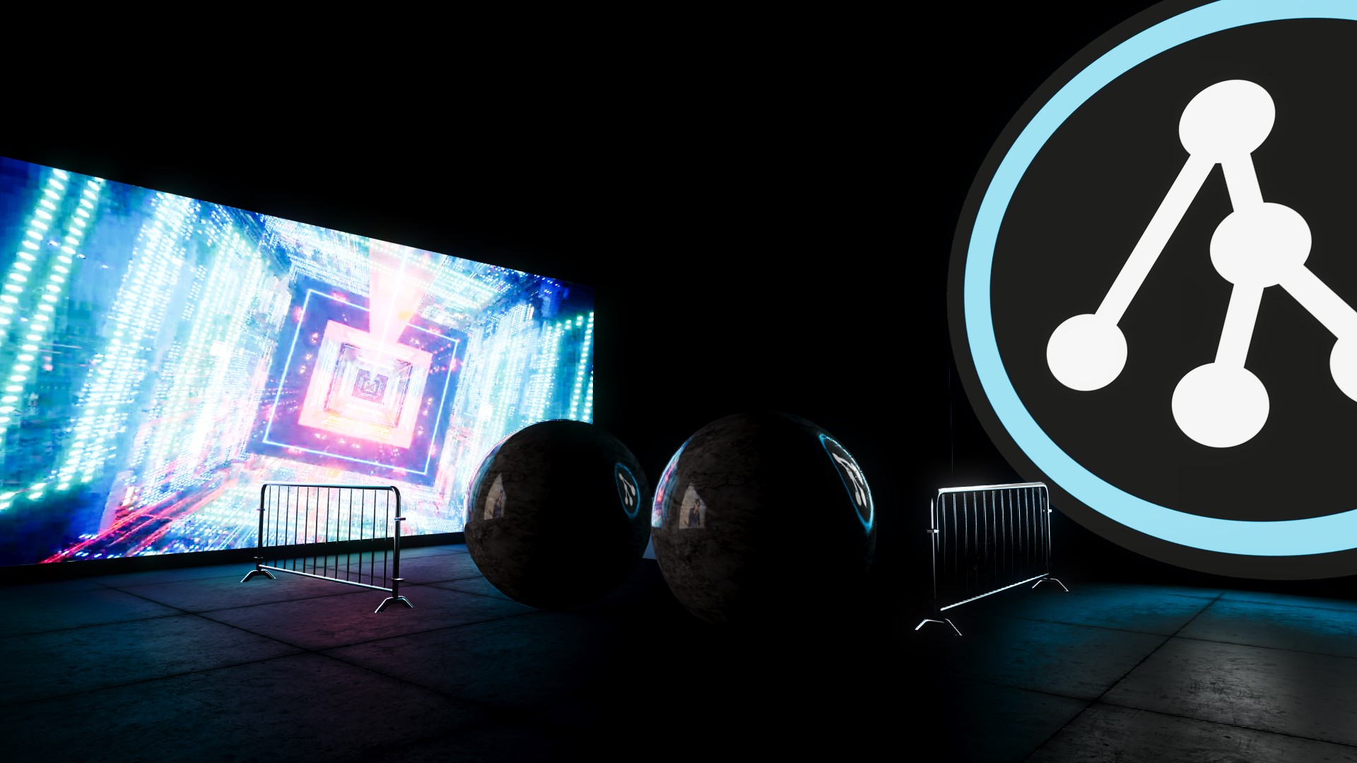
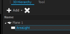
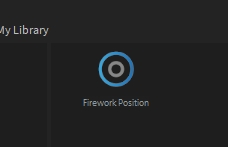
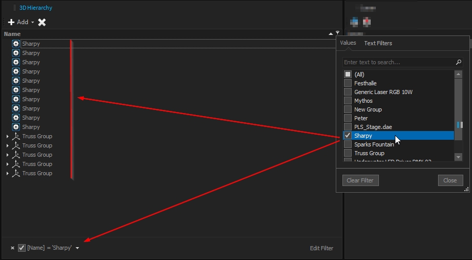
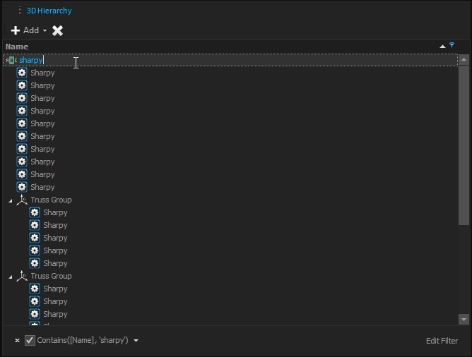
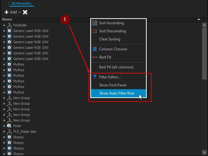
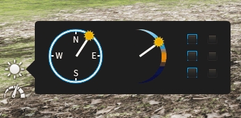
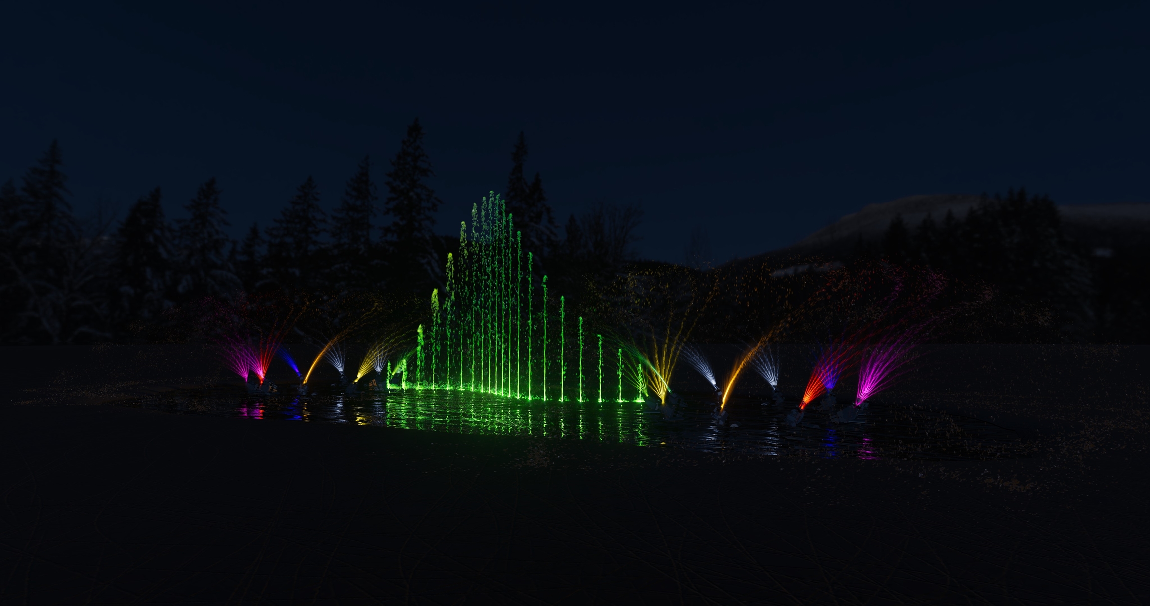
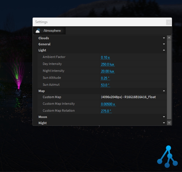
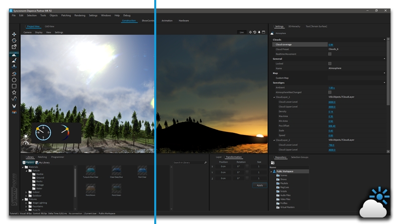
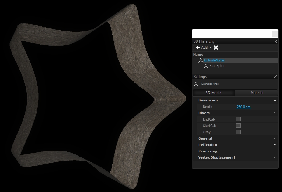
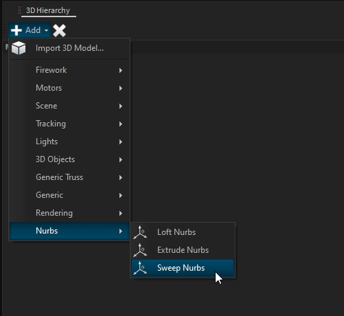
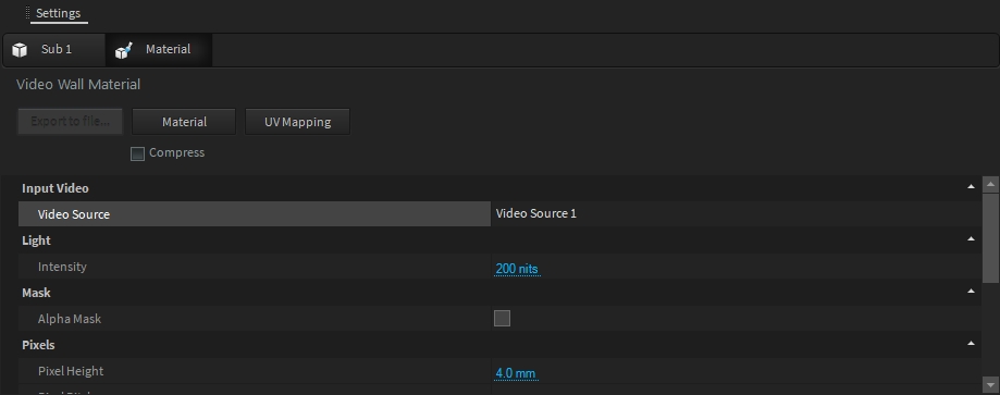
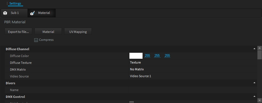
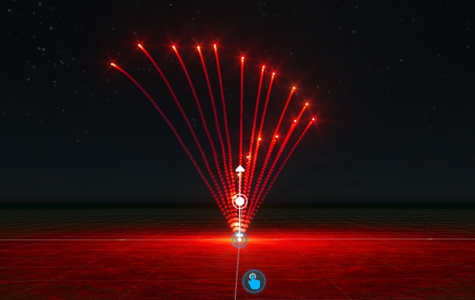
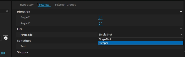
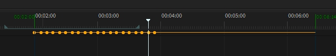
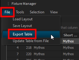
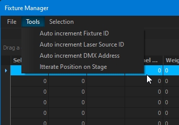
Tool Radius
Changes the radius of the tool itself.
Strength
Defines the intensity and power of each draw cycle.
Hardness
Defines the hardness/softness edges of the brush.
Height Limits
These limits can be used to make sure not to operate below or above a specific height.
Height
Rectangle Height.
Width
Rectangle Width.
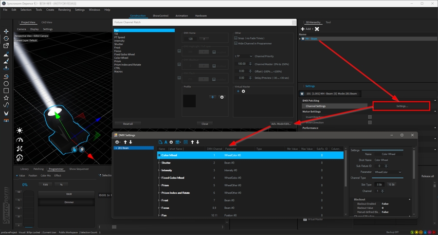
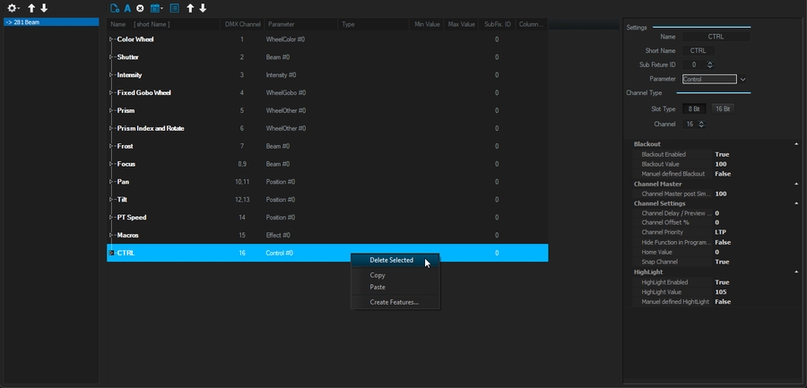
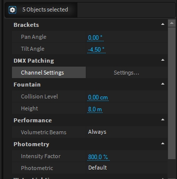
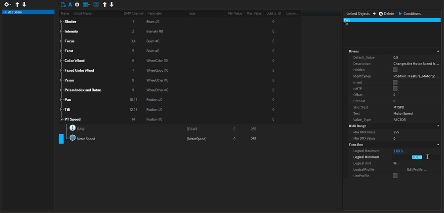
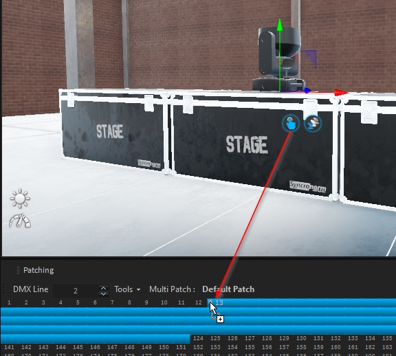
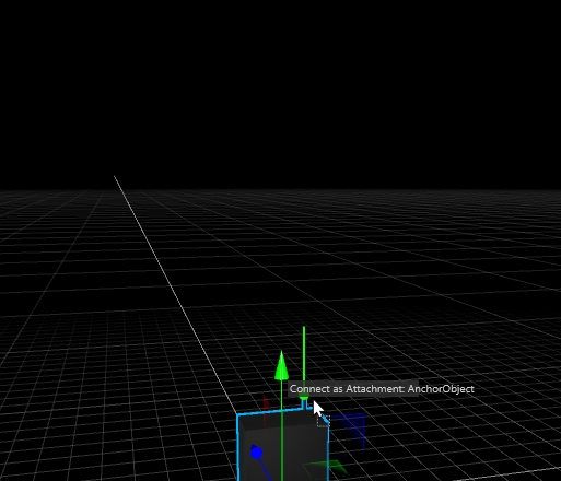
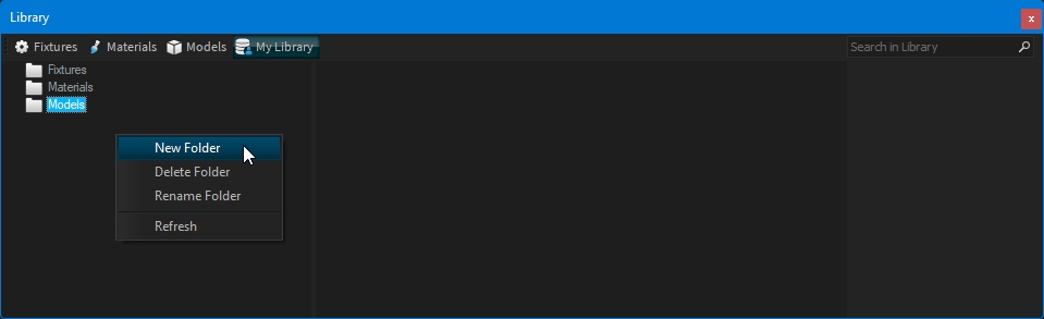
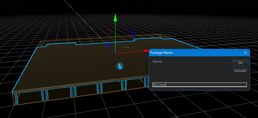
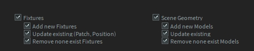
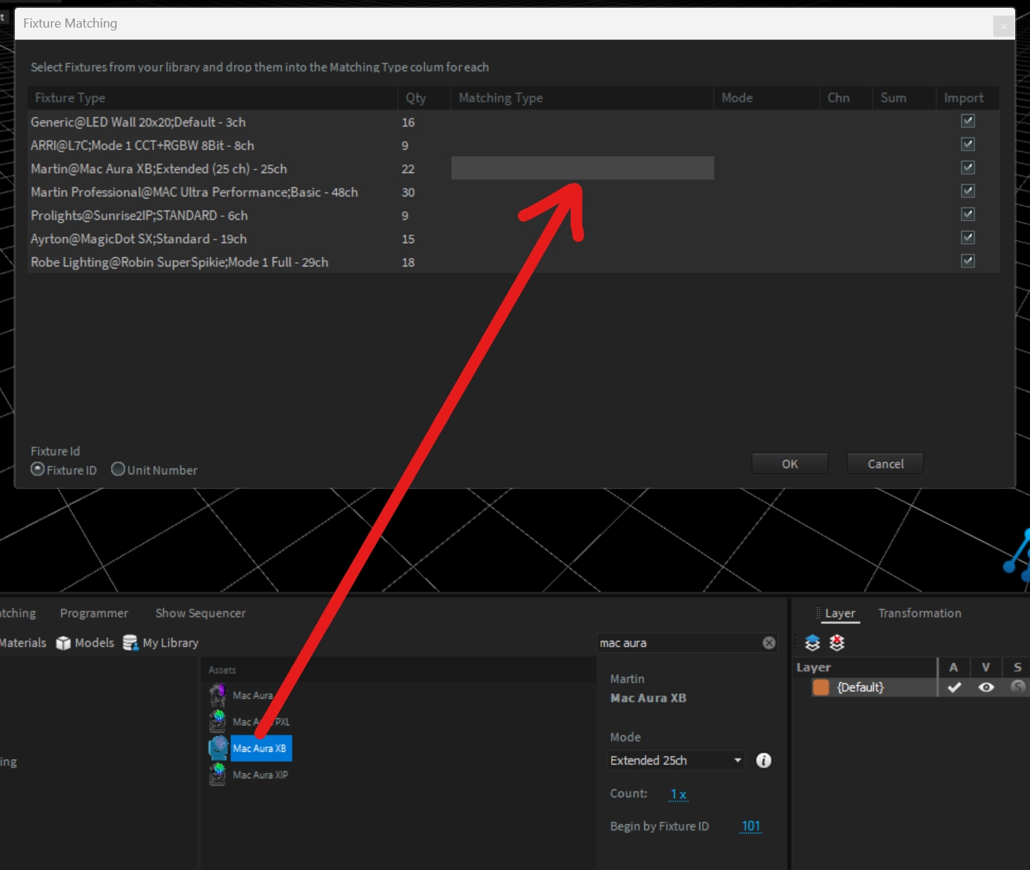
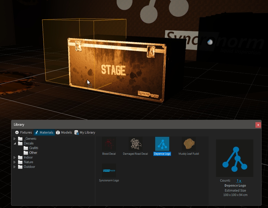
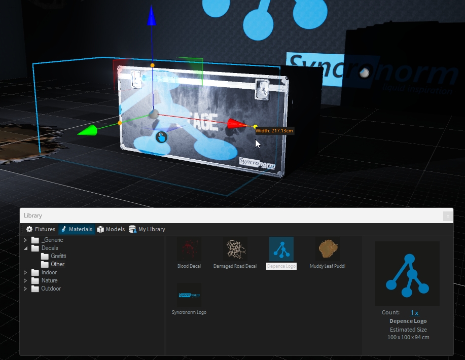
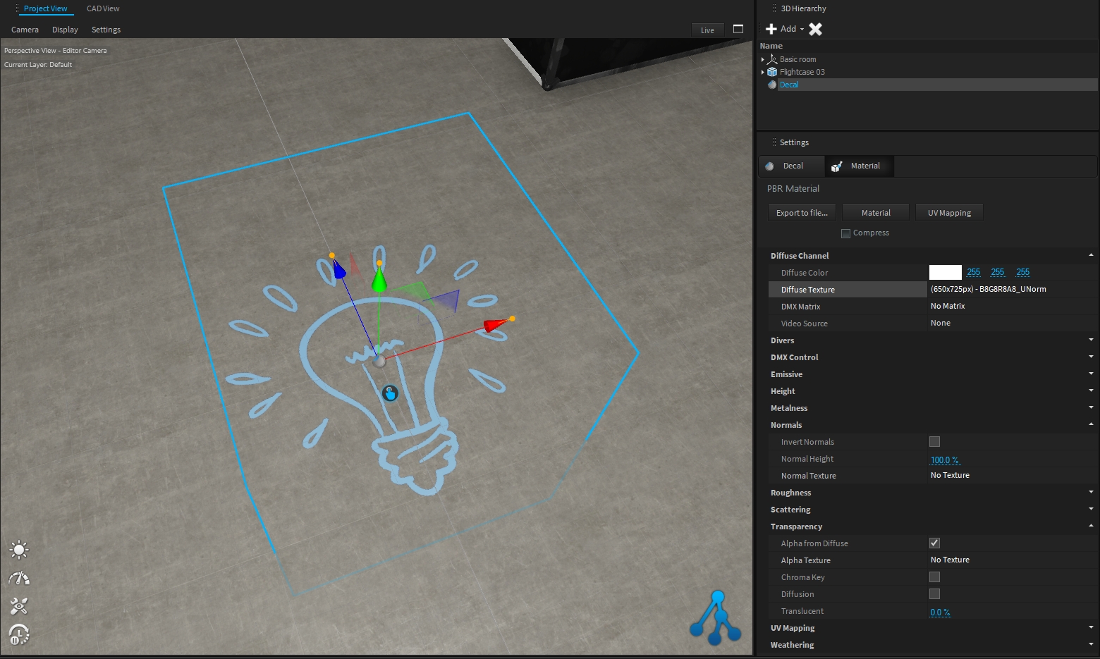
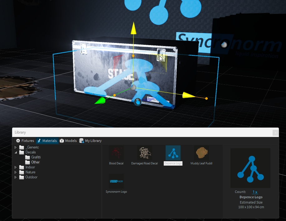
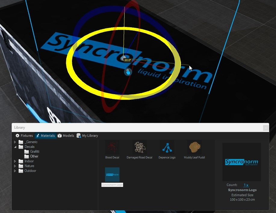
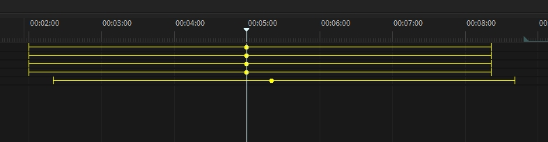
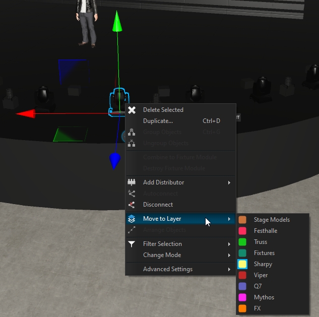
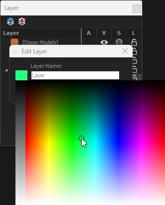
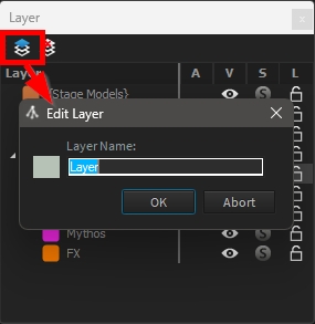

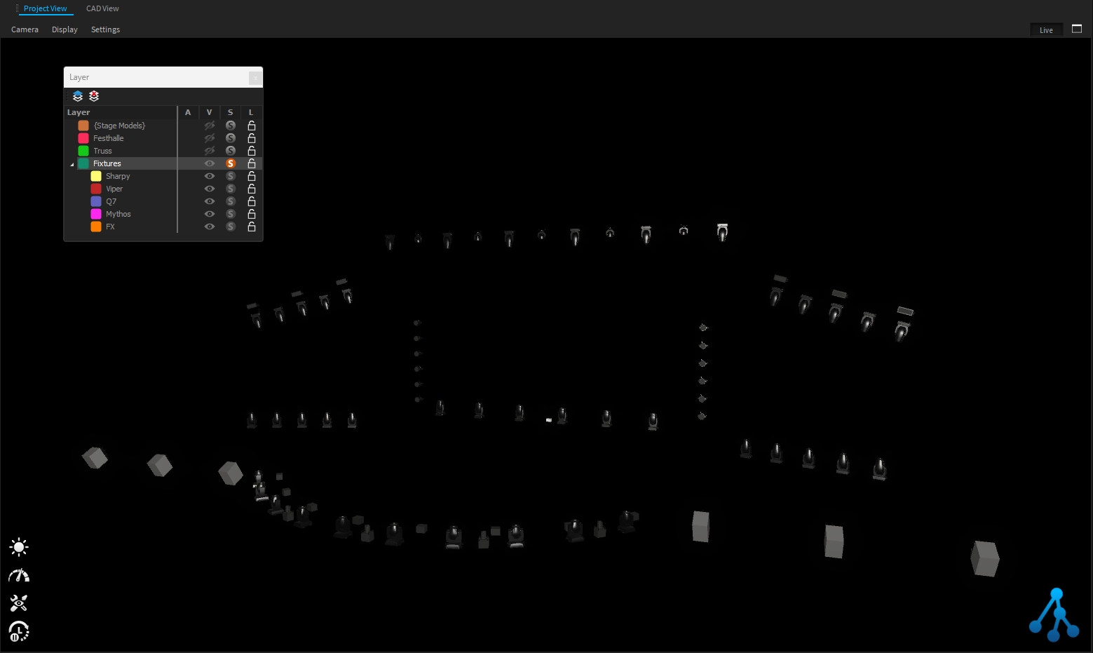

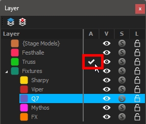
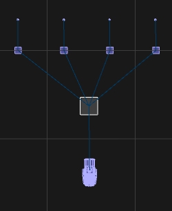
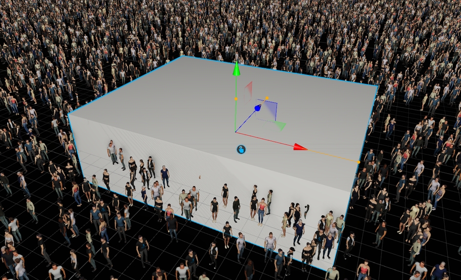
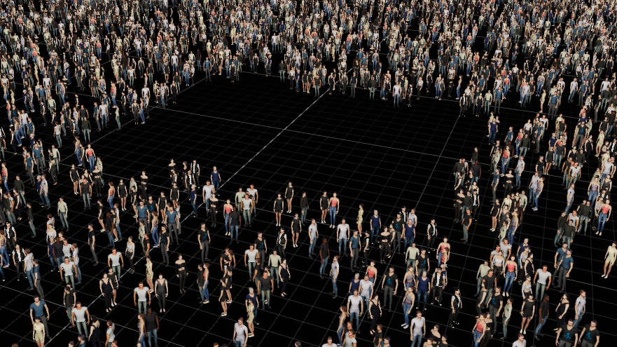
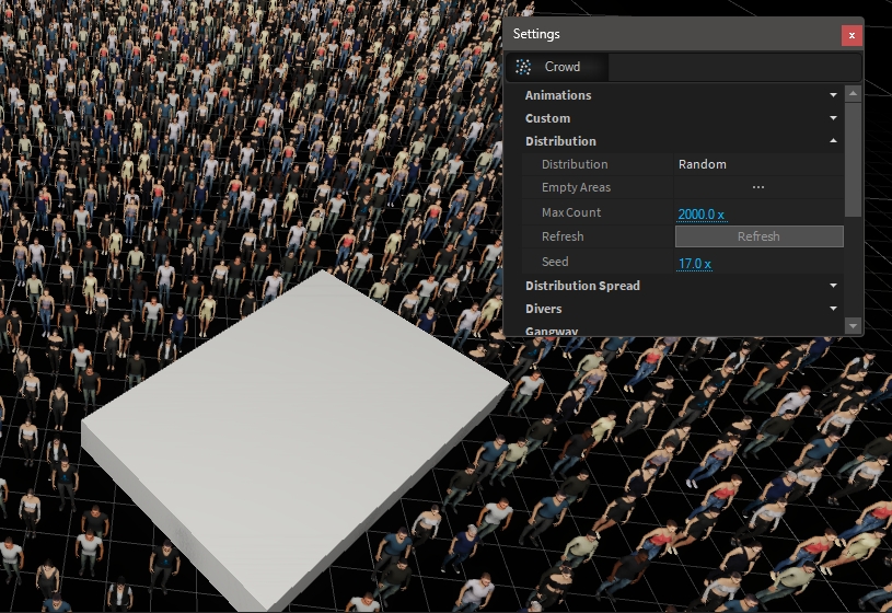
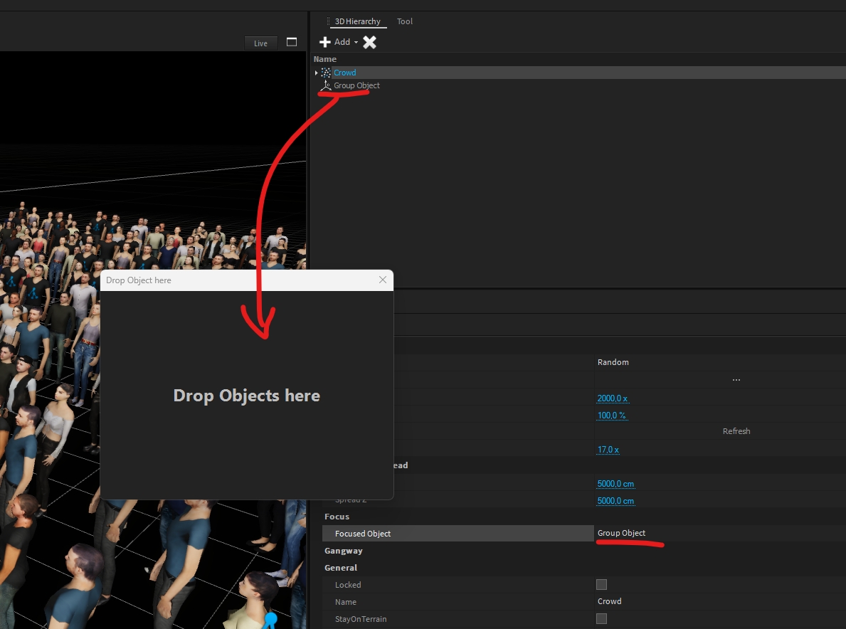
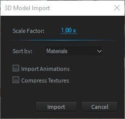
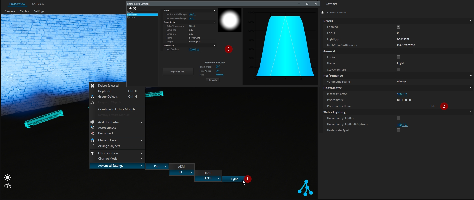
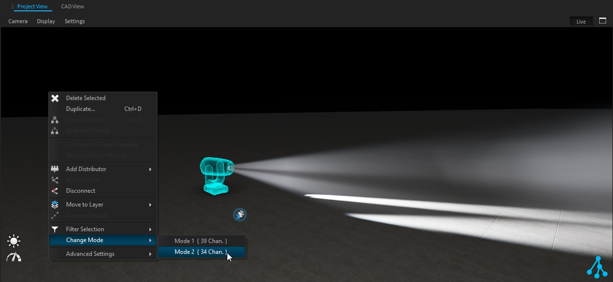
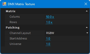
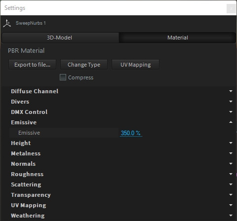
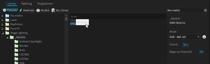
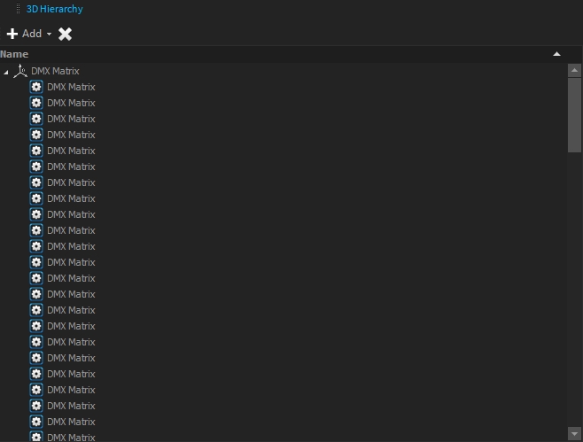
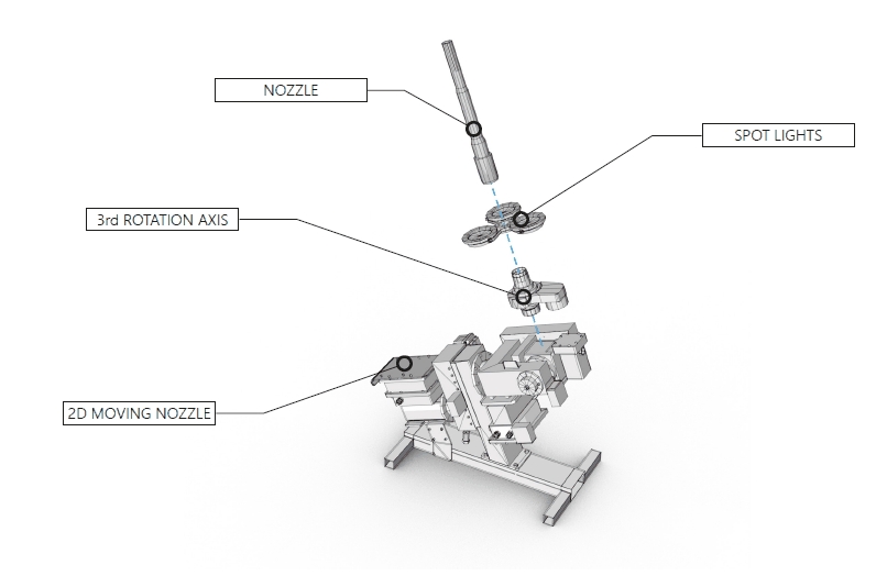
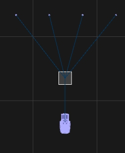
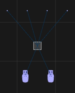
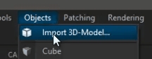
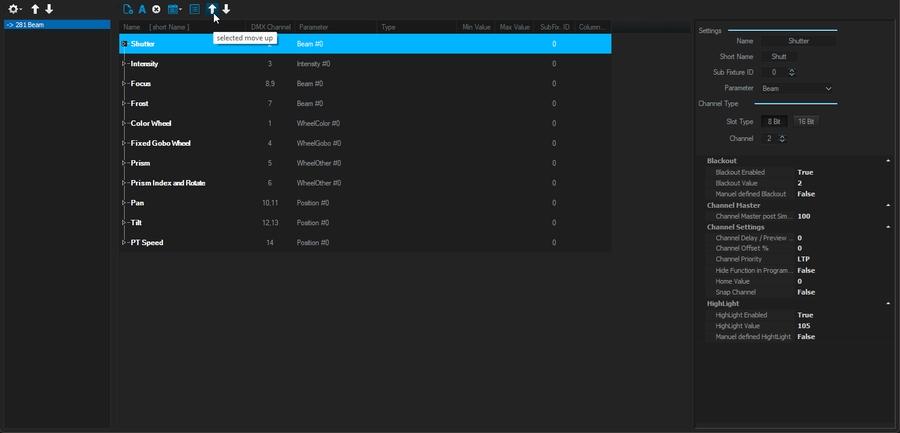
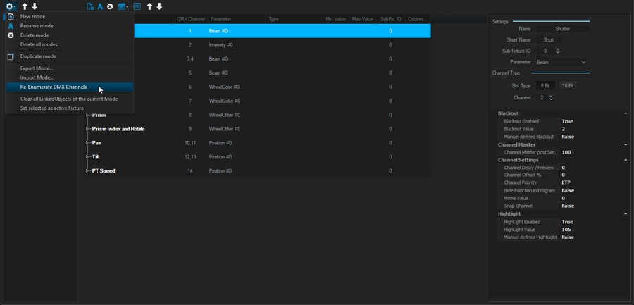
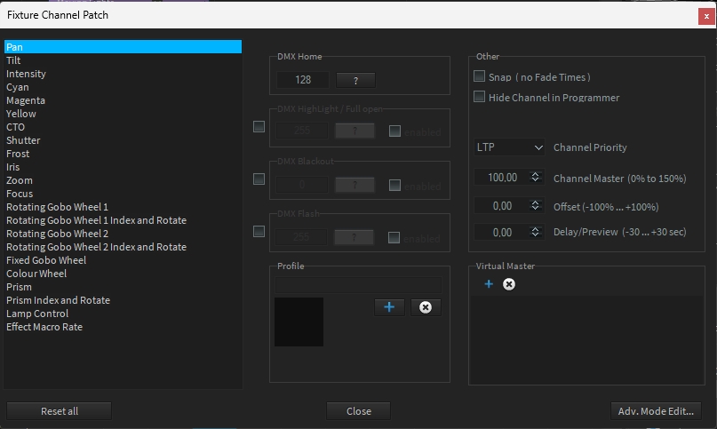
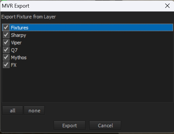
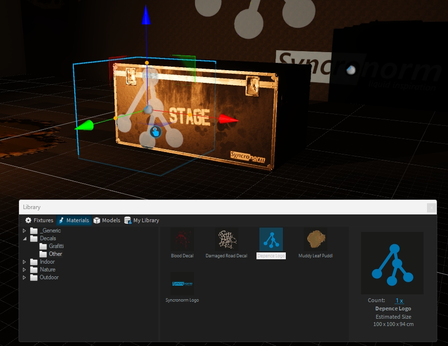
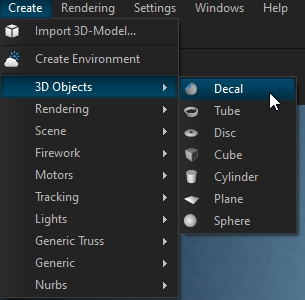
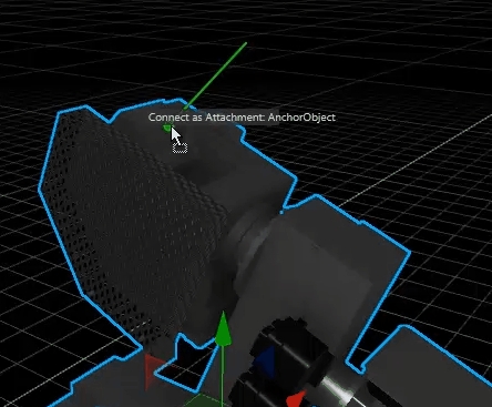
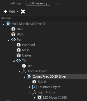
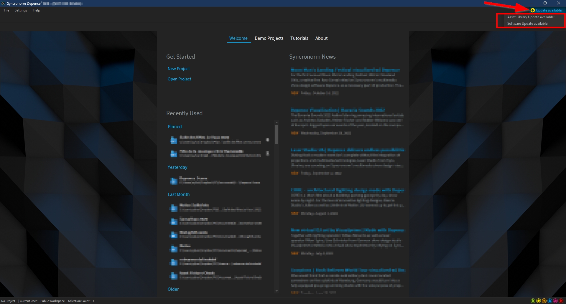
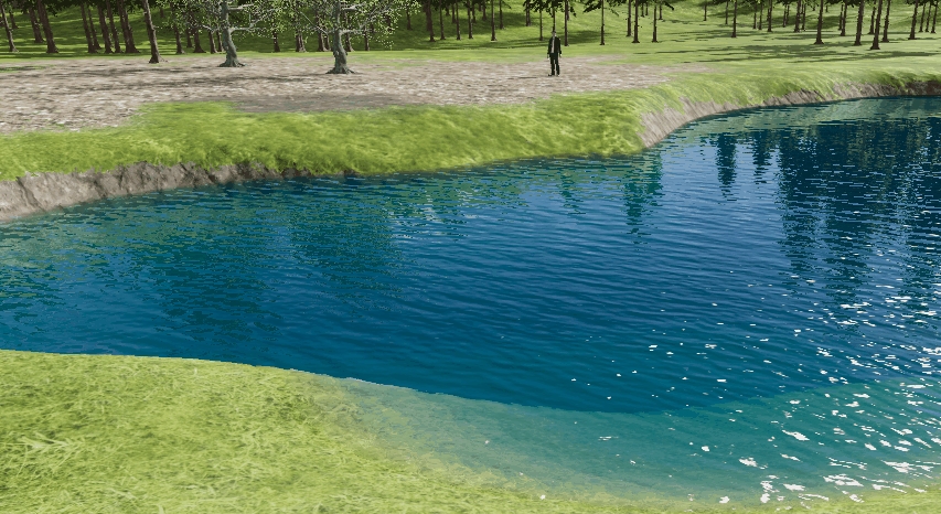
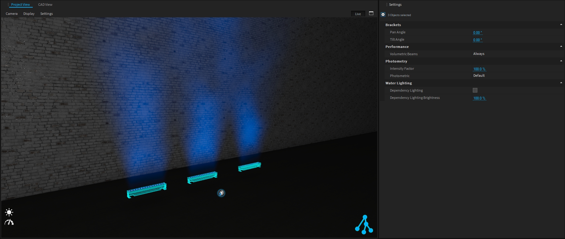
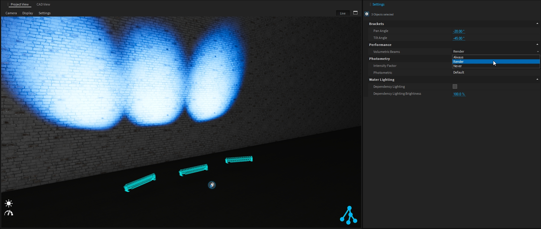
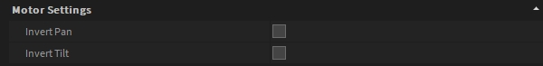
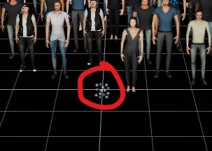
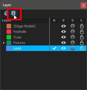
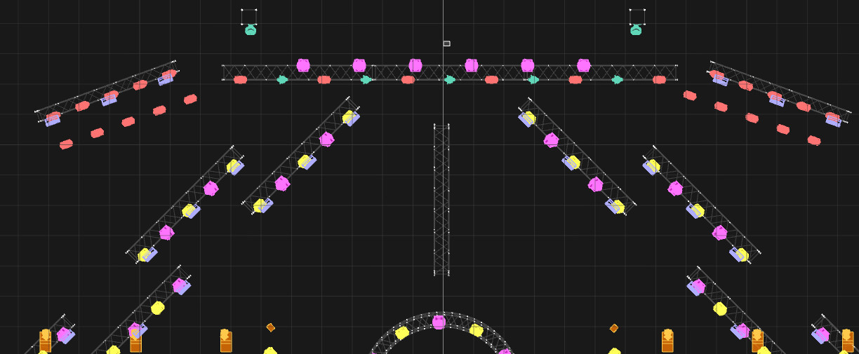
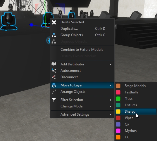
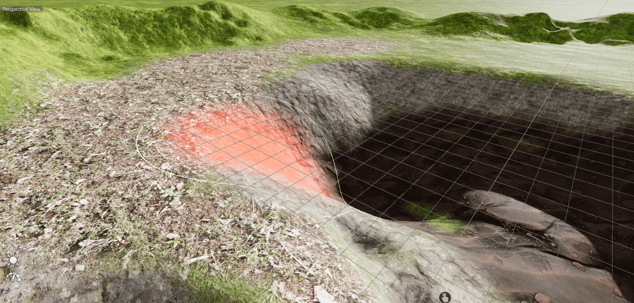
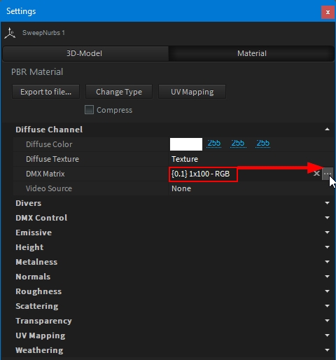
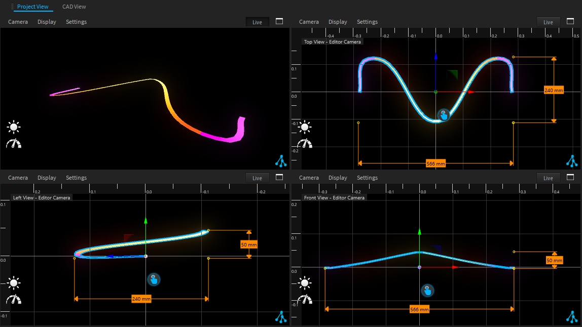
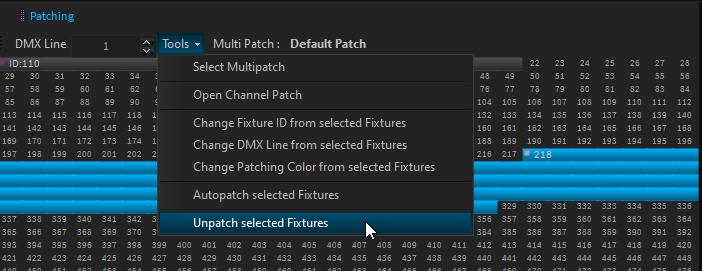

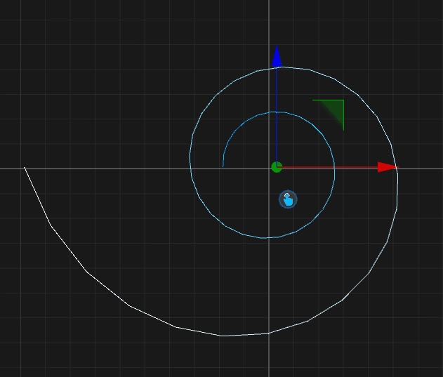
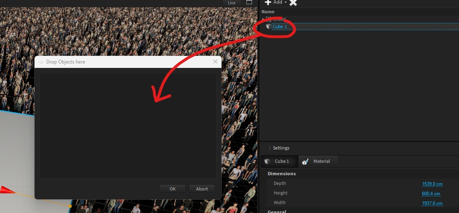
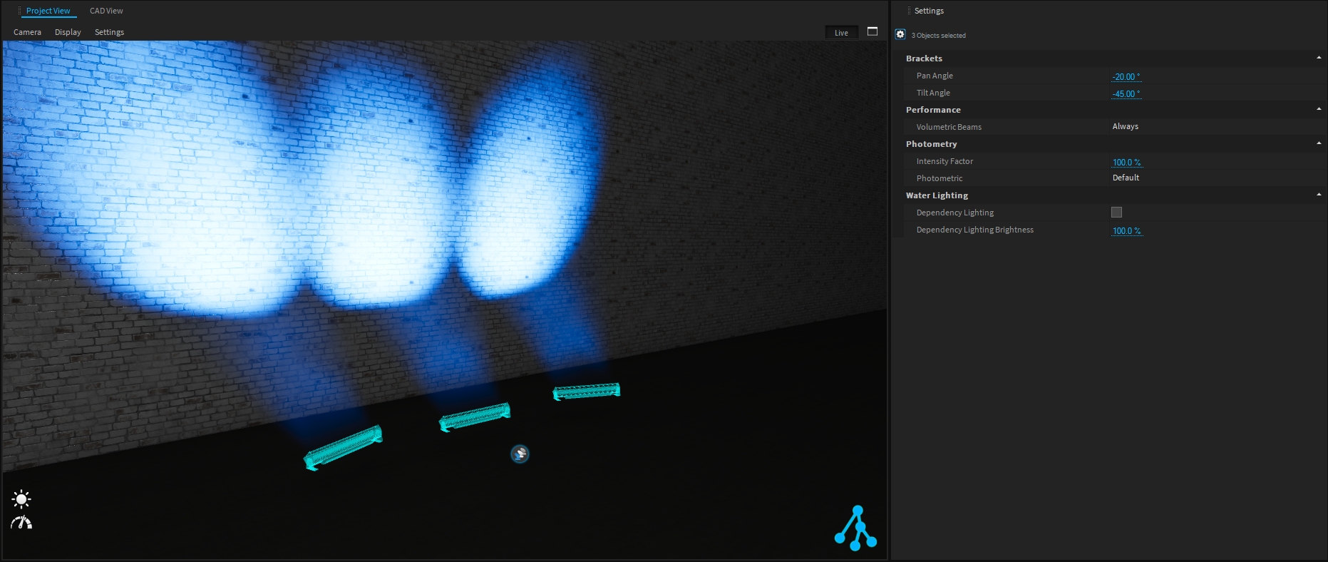
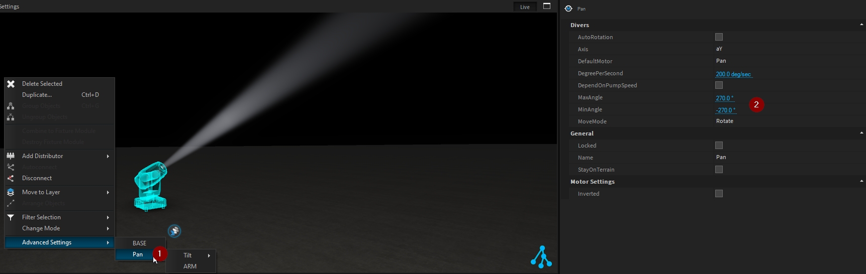
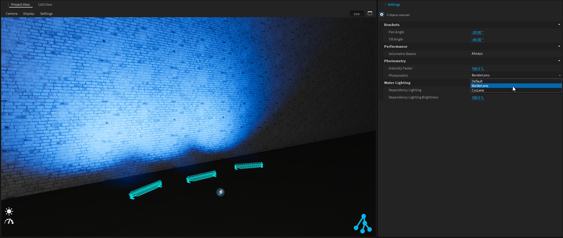
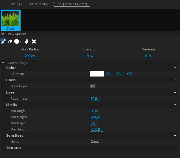
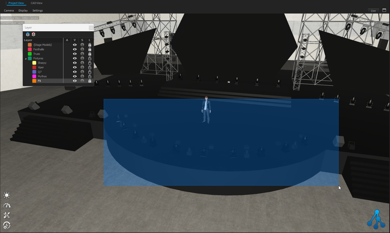
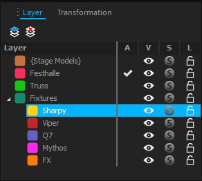
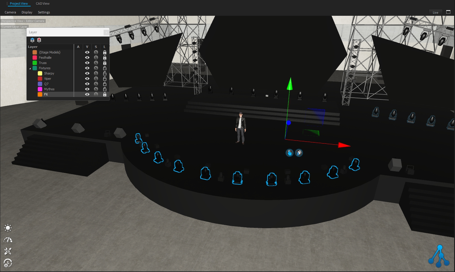
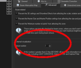


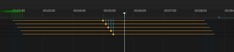
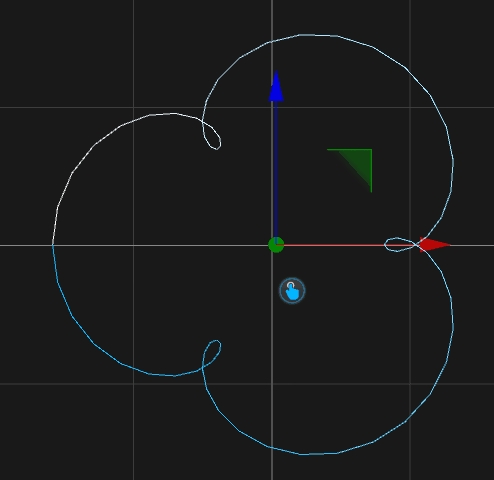
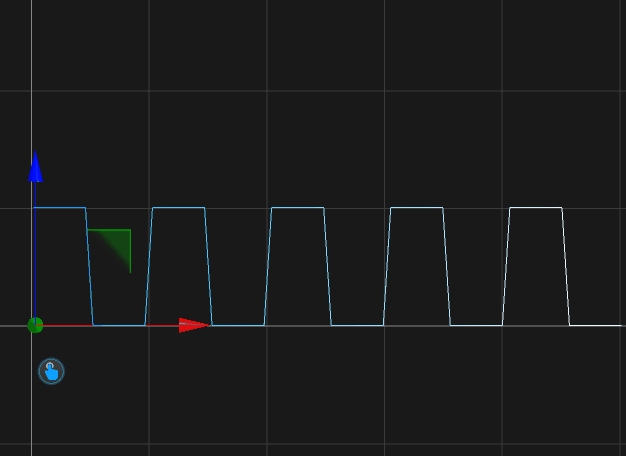
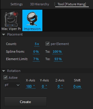
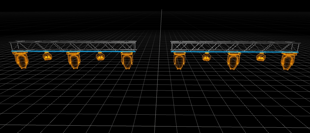
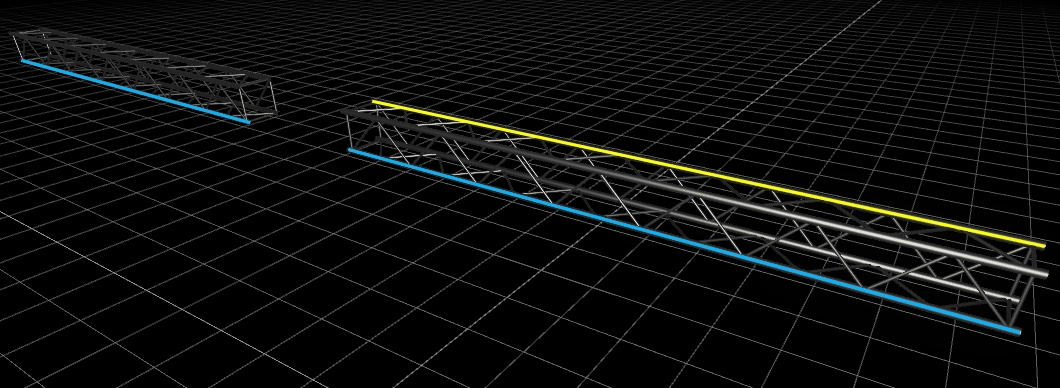
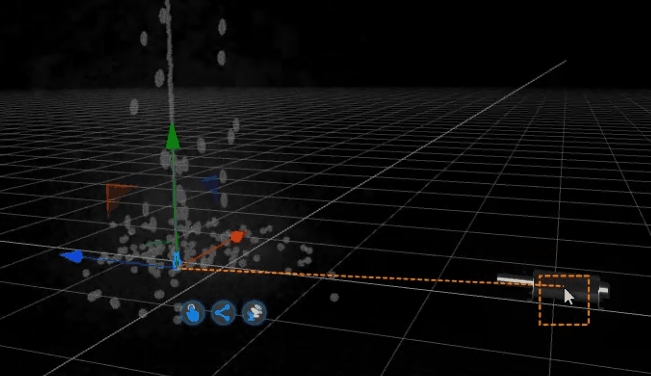
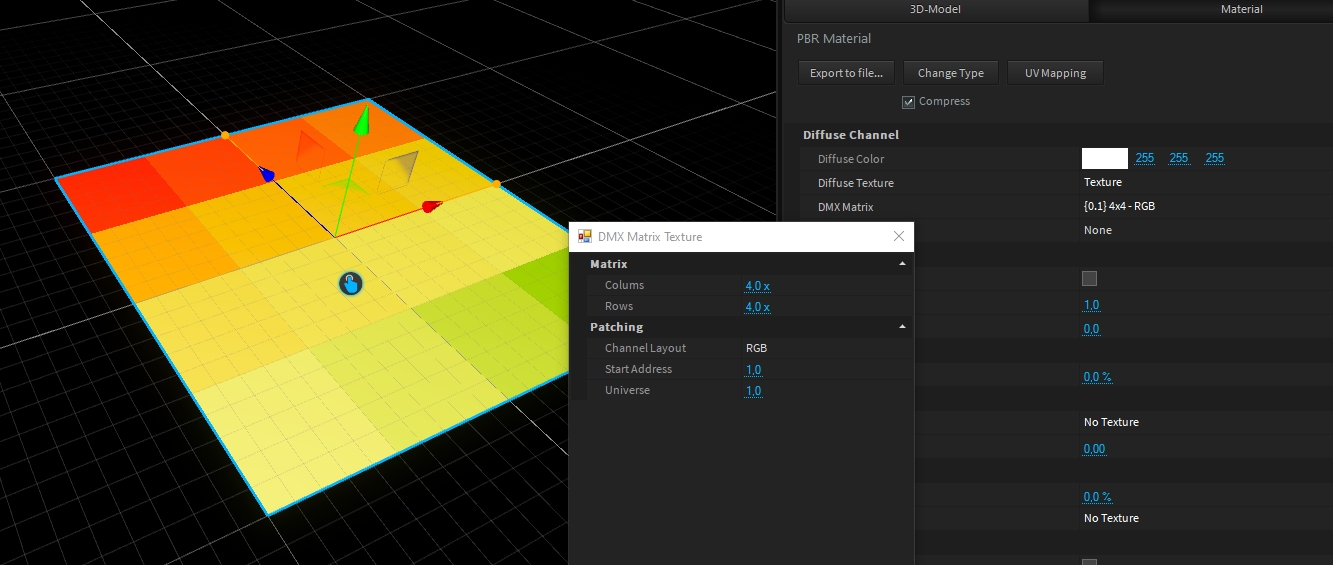
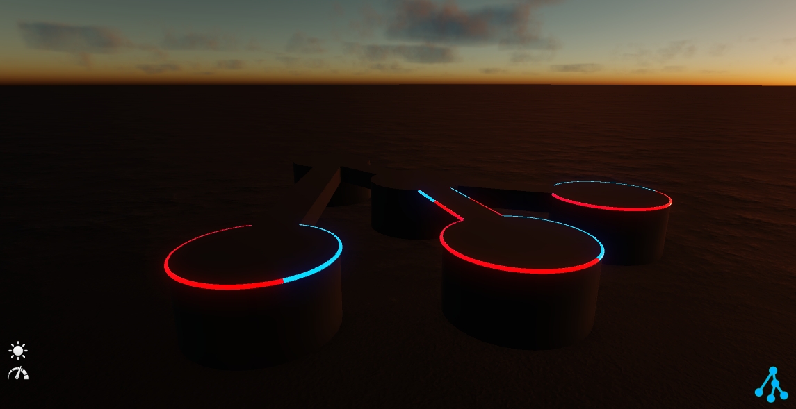
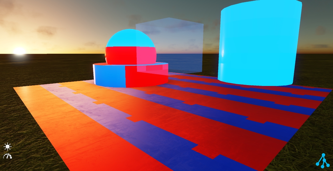
Within the Machinery library, under _Generic folder, you can find several DMX motor types. There are typically used for stage automation (moving truss, moving platforms, etc ...)
Following your automation needs (only translation or rotation, or combined), we have designed several motor types:
Each motor type contains a small 3D cube (10cm) to easily localize the motor origin (this last does not cast shadows for rendering, but can still be deleted if needed):
To adjust the translation/rotation range(s), or speed(s), please read the Lighting Fixtures Settings.
This motor type is designed to control a translation movement (Y axis per default (vertical))
1
0-255 (128)
Controls motor position from min to max
(default is -50 cm to +50 cm)
1-2
0-255 (128)
Controls motor position from min to max
(default is -50 cm to +50 cm)
This motor type is designed to control a rotation movement (Y axis per default (vertical))
1
0-255 (128)
Controls motor rotation from min to max
(default is -180° to +180°)
1-2
0-255 (128)
Controls motor rotation from min to max
(default is -180° to +180°)
1
0-255 (128)
Controls motor rotation from min to max
(default is -180° to +180°)
2
0 (0) 1-127 128-128 129-255
Off Endless CW rotation (min to max speed) Stop Endless CCW rotation (max to min speed)
1-2
0-255 (128)
Controls motor rotation from min to max
(default is -180° to +180°)
3-4
0 (0) 1-127 128-128 129-255
Off Endless CW rotation (min to max speed) Stop Endless CCW rotation (max to min speed)
This motor type is designed to control translation and rotation movement on all axis (X, Y, Z)
1
0-255 (128)
Controls motor position X from min to max
(default is -100 cm to +100 cm)
2
0-255 (128)
Controls motor position Y from min to max
(default is -100 cm to +100 cm)
3
0-255 (128)
Controls motor position Z from min to max
(default is -100 cm to +100 cm)
4
0-255 (128)
Controls motor rotation X from min to max
(default is -180° to +180°)
5
0-255 (128)
Controls motor rotation Y from min to max
(default is -180° to +180°)
6
0-255 (128)
Controls motor rotation Z from min to max
(default is -180° to +180°)
1-2
0-255 (128)
Controls motor position X from min to max
(default is -100 cm to +100 cm)
3-4
0-255 (128)
Controls motor position Y from min to max
(default is -100 cm to +100 cm)
5-6
0-255 (128)
Controls motor position Z from min to max
(default is -100 cm to +100 cm)
7-8
0-255 (128)
Controls motor rotation X from min to max
(default is -180° to +180°)
9-10
0-255 (128)
Controls motor rotation Y from min to max
(default is -180° to +180°)
11-12
0-255 (128)
Controls motor rotation Z from min to max
(default is -180° to +180°)
1
0-255 (128)
Controls motor position X from min to max
(default is -100 cm to +100 cm)
2
0-255 (128)
Controls motor position Y from min to max
(default is -100 cm to +100 cm)
3
0-255 (128)
Controls motor position Z from min to max
(default is -100 cm to +100 cm)
4
0-255 (128)
Controls motor rotation X from min to max
(default is -180° to +180°)
5
0-255 (128)
Controls motor rotation Y from min to max
(default is -180° to +180°)
6
0-255 (128)
Controls motor rotation Z from min to max
(default is -180° to +180°)
7
0 (0) 1-127 128-128 129-255
Off Endless CW rotation X (min to max speed) Stop Endless CCW rotation X (max to min speed)
8
0 (0) 1-127 128-128 129-255
Off Endless CW rotation Y (min to max speed) Stop Endless CCW rotation Y (max to min speed)
9
0 (0) 1-127 128-128 129-255
Off Endless CW rotation Z (min to max speed) Stop Endless CCW rotation Z (max to min speed)
1-2
0-255 (128)
Controls motor position X from min to max
(default is -100 cm to +100 cm)
3-4
0-255 (128)
Controls motor position Y from min to max
(default is -100 cm to +100 cm)
5-6
0-255 (128)
Controls motor position Z from min to max
(default is -100 cm to +100 cm)
7-8
0-255 (128)
Controls motor rotation X from min to max
(default is -180° to +180°)
9-10
0-255 (128)
Controls motor rotation Y from min to max
(default is -180° to +180°)
11-12
0-255 (128)
Controls motor rotation Z from min to max
(default is -180° to +180°)
13-14
0 (0) 1-127 128-128 129-255
Off Endless CW rotation X (min to max speed) Stop Endless CCW rotation X (max to min speed)
15-16
0 (0) 1-127 128-128 129-255
Off Endless CW rotation Y (min to max speed) Stop Endless CCW rotation Y (max to min speed)
17-18
0 (0) 1-127 128-128 129-255
Off Endless CW rotation Z (min to max speed) Stop Endless CCW rotation Z (max to min speed)
If needed, you can add motor into another motor.
If you do not see them independently in the programmer, it can comes because the programmer view mode is set to Combine Modules.
Switch the programmer view mode to Single View Mode to see all of them:
As any object in the 3D Hierarchy, the position of object are relative to its parent (see Transformation for deeper information).
In other words, when you use motors, you have to take a special care to the transformation applied on the tree where your object(s) is(are).
In a general manner, the origin of your object should be the same than your motor:
Then, you can safely move the motor, containing your truss (and its fixture), at the right location.
ALT key is your best friend when you move object in the 3D Hierarchy (it keeps the original transformation when dragging and dropping object)
If you moved your object inside the motor, it can result to an unwanted result as following:
By default, each 3D Model has a bound PBR Material. This Material contains all settings and texture channels. To apply an existing library material to a 3D Model, simply drag & drop material from the library over the 3D model in the viewport.
When selecting your 3D-Model, you can find the Material settings in the Settings window:
The PBR material consists of 6 different channels: Albedo, Height, Normals, Metalness, Roughness, and Emissive. Most of these channels offer a texture channel along with an offset value.
This represents the base color of the material. This can be a solid color or a texture.
All differences in reflectance and absorption of natural surfaces can be split into two different types: Electric (Metals) and Dielectric (Plastics, Fabric, etc.). The Metalness value defines the transition between these types. 0=Dielectric 100%=Metallic
The Roughness channel describes how rough or smooth the surface is, which has a big influence on how it reflects the light and environment. 0%=smooth (like a mirror), 100% = full rough (like a paper)
Normal Maps are used to add 3D details to the surface. These normal maps store a surface normal vector in tangent space. While Depence² uses a left-handed coordinate system it uses the following normal map orientation: Red=X+ Green=Y- Blue=Z+. Depence uses "DirectX-style" normal maps which are -Y:
In addition to Normal Mapping the Heights are used to create the 3D illusion of bigger high detailed structures. Therefore a grayscale image is used where Black = lowest height and White = Max Height
The UV-Mapping of a 3D Model defines how a texture will be applied on models polygons. These UV's are usually stored within the 3D-Model. In some cases, these won't be scaled correctly. Therefore each material has additional properties:
This option allows to make an object transparent or masked out by an alpha mask.
Once an object is rendered with transparency, the lighting calculations having a huge performance impact. This scales with the number of light & transparent objects. So only use transparency when really necessary and on few objects.
These properties create a procedural wetness effect on the surface.
UV Scale
Scales the texture on the model.
UV Offset
Moves the texture on the model.
Texture Mapping
UV Mapping: Uses default mapping.
Box-Mapping: Computes UVs in a Box perspective.
Tile-Size
When using Box-Mapping this defines the size in square meters of one tile.
Animate UV
constantly moves the UV coordinates by the UV-offset values
Translucent
makes the object transparent *
Alpha Texture
Mask out an object based on a black/white texture
Alpha from Diffuse
Uses the alpha channel from the Diffuse texture for masking
Diffusion
Creates kind of milky glass effect depending on the roughness