ModBus
The integration and management of ModBus values, whether from sensors or other units, into a DMX system are crucial. By employing specific techniques and procedures, as demonstrated in our examples, you can efficiently receive and process these values. Proper handling of DMX addressing and device assignments is vital to ensure all data is routed and utilized correctly.

Description
With Depence 3 and the vServer 4, you can connect SPS Units that support the Modbus Protocol for controlling devices like frequency converters or pumps, or for querying sensor values.
For this, patched DMX channels are connected with ModBus output modules, or ModBus input modules are connected with patched DMX channels.
As prescribed by the ModBus protocol (please refer to specialized literature on ModBus for further information), you can send binary (QX) or analog values (QW or QD) to the respective ModBus modules, or receive binary (IX) or analog values (IW or ID) from the corresponding ModBus modules.
Add ModBus Units
You can address multiple ModBus Units (CPU) and configure them individually. Each ModBus CPU is addressed over the network using a network IP address. The network port for ModBus is static and standardized, set to 502.
Send ModBus Values
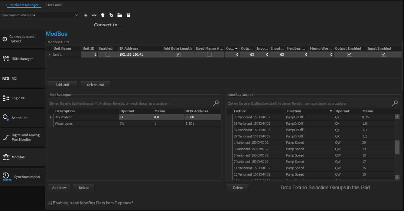
To send a Pump On/Off DMX channel and a Pump Speed channel via ModBus, follow the procedure shown in the illustration. First, create a new ModBus Unit using the "Add Unit" feature and enter the IP address set on the CPU. Now, drag and drop a SelectionGroup with the corresponding devices from the SelectionGroup window into the ModBus Output table. For a binary switch (On/Off), set the operand to QX and for an analog PumpSpeed channel, set the operand to QW. In the Memo column, set the appropriate ModBus memory area; for example, for the QX, set the Memo address to 0.0 (Word 0 Bit 0) and for the Pump Speed (QW) to address 20. Continue with other devices as previously described.
Receiving ModBus Values
If you wish to receive ModBus values, such as sensor readings for water level, dry-run protection, temperature, or humidity, follow these steps:
All incoming values must be routed to a DMX address. To do this, a device capable of accepting this DMX value must be located at the respective DMX address. Only in this way can the values be further processed later in the "Logic Module" or "Live Panel".
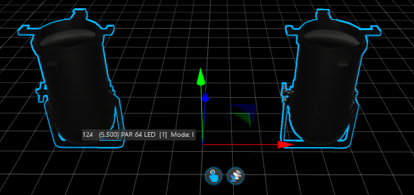
In our example, a sensor value for dry-run protection (binary) IX and a water level value (analog) IW have been defined. Use the "AddNew" option below the ModBus Input table to add the corresponding entry. In our example, we routed the incoming values for "Dry Protect" to DMX address Universe 5 and Address 500 (5.500) and for the "Water Level" to 5.501. It is advisable to simply patch 2 single-channel PAR spots to these addresses in order to work with the input values further.

Routing to Virtual Master
In the following LogicModule connection example, you can see how the "Dry Protection" input value from ModBus, written to DMX address 5.500, has been linked and used with a "Virtual Master."
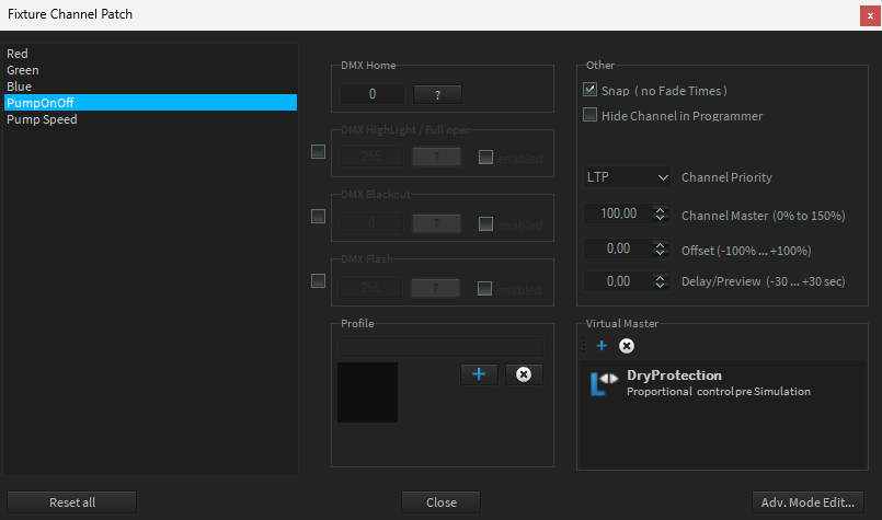
For safety reasons, the input value is passed through a hysteresis. This allows for precise determination of the switching point for analog values. The 'not' function, if necessary, inverts the value (depending on the state received from ModBus) and then forwards it to the virtual master. The Virtual Master then needs to be connected to the appropriate Pump On/OFF channels in the "Channel Settings" (see the next illustration)

