Schematic Views
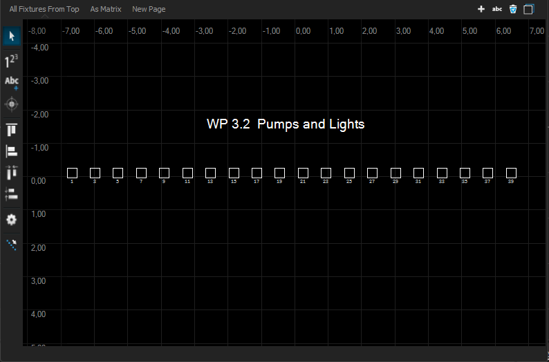
The Schematic Views, from menu Windows > Schematic Views, are an extended feature to place your fixtures on a virtual 2D plan, where fixture positions are not bound to their world coordinates. The same fixture can exist on several views in different arrangements. This makes it easy to apply for different selection orders and use the graphical selection tools.

Move the grid with the right mouse button pressed.
Use the mouse wheel to enlarge or reduce the view. (Zoom)

In the upper area you will find the tab listing of all Schematic pages. To the right are the options to create new pages, rename, delete and duplicate.
On the left edge is the toolbar with different tools for selecting and aligning the elements.
![]() Numbering Tool
Numbering Tool
![]() Add Text Lines to the Page
Add Text Lines to the Page
![]() Brings the selected Fixtures to the center of the View
Brings the selected Fixtures to the center of the View
![]() Align top and left flush.
Align top and left flush.
![]() Aligns all selected fixtures evenly between the left and right or top and bottom fixtures.
Aligns all selected fixtures evenly between the left and right or top and bottom fixtures.
![]() Displays the properties of the page in the Settings window.
Displays the properties of the page in the Settings window.
![]() Opens the Fixture Selection Tool
Opens the Fixture Selection Tool
Add Fixtures to a Schematic View
There are several possibilities for placing devices in the schematic view.
Drop selected fixtures from the Project View or from the CAD view onto the Schematic View Page.
Drop a fixture group from the Selection Group window onto the Schematic View Page.
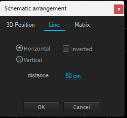
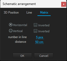
In both cases you will now be asked from which 3D view you would like to have the fixtures aligned on the page.


Select any option here and confirm it with OK
Afterwards, you can place each fixture as you wish.
If you do not see any fixtures, zoom out or press the "Center Selection" button. The fixtures are set to their original world coordinates the first time they are placed. These can lie outside the current range of vision.
Select Fixtures
When you create effects (waves or runs), they depend on the selection order. You determine the selection order by clicking on the desired fixtures one after the other. Depence then assigns a consecutive number to the corresponding fixture. This number will later be the sequence in your effect.
When you draw a frame around the fixture symbols, the way you draw the frame is important. If you draw the frame from left to right, the fixtures will also be numbered from left to right. If you drag the frame from right to left, the fixtures will be numbered from right to left. The same applies to top to bottom and bottom to top.

The blue filling and the index above the symbol also show you in which order you have selected.
Double selection
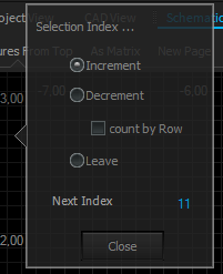
To programme more complex sequences, it is helpful to assign sequences twice. To do this, you can use the Numbering Tool to set the pointer for the next index to any value.

To recreate this example, first select the left 5 fixtures with a frame selection from left to right.
Then click on the Numbering Tool ![]() und setzten den
und setzten den

To recreate this example, first select the left 5 fixtures with a frame selection from left to right.
Then click on the Numbering Tool and set the value for Mesh Index to 1 again.
Now drag a frame from right to left over the right 5 fixtures.